Sunday, December 1, 2013

Implementing AAA Services on IOS Devices with RADIUS and TACACS

December 2013 • 7 min read

In modern enterprise networks, robust user authentication and access control mechanisms are critical to maintaining a secure infrastructure. Cisco IOS devices offer support for Authentication, Authorization, and Accounting (AAA) services, which enable administrators to enforce consistent access policies and monitor network usage. Two widely adopted AAA protocols in IOS environments are RADIUS and TACACS+.

Understanding AAA

AAA stands for Authentication, Authorization, and Accounting:

  • Authentication verifies a user's identity before granting access to network resources.
  • Authorization determines what an authenticated user is allowed to do.
  • Accounting tracks what users do on the network, including commands entered and sessions initiated.

RADIUS vs TACACS+

Both protocols are used to implement AAA, but they differ in how they handle communication and capabilities:

  • RADIUS (Remote Authentication Dial-In User Service) combines authentication and authorization in a single process. It uses UDP and is widely used for network access authentication (e.g., VPN, Wi-Fi).
  • TACACS+ (Terminal Access Controller Access-Control System Plus) separates all three functions (authentication, authorization, accounting), uses TCP, and provides more granular command-level control. It is typically preferred for administrative access control on IOS devices.

Configuring AAA on Cisco IOS

To begin using AAA services, you must first enable AAA on the device:

Router(config)# aaa new-model
  

Configuring RADIUS

Add a RADIUS server and define its shared secret:

Router(config)# radius-server host 192.168.1.10 key radiusSecret
Router(config)# aaa authentication login default group radius local
  

Configuring TACACS+

For TACACS+, define the server and set up the AAA method:

Router(config)# tacacs-server host 192.168.1.20
Router(config)# tacacs-server key tacacsSecret
Router(config)# aaa authentication login default group tacacs+ local
  

Fallback Authentication

In both cases, using local as a fallback ensures access if the external server is unavailable.

Authorization and Accounting Examples

To authorize exec shell access and account for user commands:

Router(config)# aaa authorization exec default group tacacs+ local
Router(config)# aaa accounting exec default start-stop group tacacs+
  

Use Cases and Deployment Considerations

RADIUS is ideal for end-user authentication, such as wireless access or VPN logins. TACACS+ is preferred for network device management due to its superior command control and logging granularity. Enterprises often deploy both simultaneously, using RADIUS for end-user access and TACACS+ for admin access.

Best Practices

  • Use encrypted transport and strong shared secrets.
  • Segment AAA traffic on a dedicated management network.
  • Regularly audit AAA logs to detect anomalies.
  • Ensure backup user access methods are available.
 
✅ Want to improve your network security posture?
Try implementing AAA services in your test environment to gain better visibility and control.


Eduardo Wnorowski is a network infrastructure consultant and technologist.
With over 18 years of experience in IT and consulting, he brings deep expertise in networking, security, infrastructure, and transformation.
Connect on Linkedin

Friday, November 1, 2013

Reducing Network Convergence Time with Bidirectional Forwarding Detection (BFD)

November 2013 - Reading time: 8 minutes

In today's high-availability networks, the speed at which routing protocols detect and react to failures is a critical factor in overall performance. Traditional protocol timers—especially in protocols like OSPF, EIGRP, and BGP—may take several seconds to detect a link failure, potentially impacting critical applications and user experience. Enter Bidirectional Forwarding Detection (BFD), a lightweight, fast failure detection mechanism that enhances convergence times by providing rapid detection of link or path failures independently of the routing protocol.

Understanding the Convergence Problem

Routing convergence refers to the process of detecting a network topology change and updating the routing tables across all affected routers. This process typically involves failure detection, routing protocol recalculations, and eventual stabilization. When a primary link fails, conventional timers like dead intervals or hold timers can delay failure recognition, especially in large or diverse networks.

For example, OSPF typically uses a hello interval of 10 seconds and a dead interval of 40 seconds. That means it may take up to 40 seconds before a router notices a neighbor has gone down—far too long for VoIP, video, or transactional applications.

Introducing Bidirectional Forwarding Detection

BFD is designed to detect forwarding failures between two devices in milliseconds, regardless of the underlying forwarding mechanism or routing protocol. It works by sending control messages between two systems, forming a session for each direction of traffic. These control packets can be sent as often as every few milliseconds, enabling failure detection in under 50ms when configured appropriately.

The key value of BFD lies in its protocol-agnostic nature—it doesn’t replace routing protocols but enhances them. BFD notifies the routing protocol immediately upon session failure, which in turn triggers faster route recalculations and convergence.

BFD Modes: Asynchronous vs. Demand

  • Asynchronous Mode: The most common, where each device periodically sends BFD control packets. Failure is detected when packets stop arriving.
  • Demand Mode: Designed for cases where traffic flows continuously and BFD sessions are assumed healthy as long as user traffic is received.

Asynchronous mode is typically preferred in most enterprise and service provider environments due to its explicit control messaging and simplicity.

Configuration Example: Cisco IOS

Let’s walk through a sample configuration of BFD for OSPF between two Cisco routers:

interface GigabitEthernet0/0
 ip address 10.1.1.1 255.255.255.0
 bfd interval 50 min_rx 50 multiplier 3

router ospf 1
 network 10.1.1.0 0.0.0.255 area 0
 bfd all-interfaces
  

This configuration sets up BFD with a 50ms transmit and receive interval and a multiplier of 3, meaning the session is considered down if three consecutive packets are missed (i.e., 150ms detection).

Considerations and Best Practices

  • Hardware Support: Ensure your devices and platforms support BFD natively, especially in hardware forwarding paths.
  • CPU Load: Excessively aggressive BFD timers may increase CPU usage; test before deploying in production.
  • Redundancy Planning: Combine BFD with IP SLA or secondary links for robust HA design.

In high-stakes environments—finance, healthcare, e-commerce—network downtime is measured in dollars. BFD helps mitigate the impact of failures by drastically improving detection and convergence time.

Real-World Use Cases

Many service providers rely on BFD for fast failure detection in MPLS backbones. Enterprises use it to ensure seamless WAN failover using routing protocols like BGP or OSPF over redundant Internet or MPLS links. It's particularly valuable in cloud hybrid designs where multiple ISPs and tunnels are in play.

Implementing BFD across all critical paths is not only a technical win—it’s a strategic investment in resilience and uptime.


Eduardo Wnorowski is a network infrastructure consultant and technologist.
With over 18 years of experience in IT and consulting, he brings deep expertise in networking, security, infrastructure, and transformation.
Connect on Linkedin

Tuesday, October 1, 2013

Optimizing OSPF Design in Multi-Area Environments

October 2013   |   Reading Time: 10 minutes

Open Shortest Path First (OSPF) remains one of the most deployed interior gateway protocols (IGPs) in enterprise networks. When networks scale, OSPF's support for hierarchical design using areas becomes invaluable. However, poorly structured multi-area OSPF designs can create instability, introduce suboptimal routing, and complicate troubleshooting.

Why Use Multi-Area OSPF?

OSPF scales better when the link-state database (LSDB) is segmented. Area 0 serves as the backbone, and additional areas (1, 2, etc.) connect to it via Area Border Routers (ABRs). This segmentation improves convergence and limits flooding scope for LSAs.

Key Design Principles

  • Always connect non-backbone areas to Area 0: Virtual links should only be temporary workarounds.
  • Minimize ABRs: Too many ABRs can result in inconsistent LSDBs and route flapping.
  • Summarize: Use area range statements on ABRs to reduce routing table size and provide stability.
  • Plan LSAs: Understand which LSAs are injected where. Type 3 LSAs (summary) are most common between areas.

Common Pitfalls

Misunderstanding LSA propagation often causes routing loops or instability. For example, injecting Type 5 LSAs (external routes) into stub or totally stubby areas causes configuration issues. Misplacing ABRs or neglecting area summarization results in excessive LSA flooding and convergence delays.

ABR Behavior in IOS and IOS-XE

In IOS-based routers, ABR behavior is based on active interfaces belonging to multiple areas. In OSPFv2 (IPv4), at least one interface must be in Area 0. In newer platforms, ABRs behave differently when using passive interfaces — a key consideration when virtualizing edge routers.

Optimizing with Stub, Totally Stubby, and NSSA Areas

Using stub area types reduces Type 5 LSA propagation and can simplify routing decisions. NSSA areas allow redistribution of external routes without exposing the entire external LSA set to the backbone. Remember that NSSA Type 7 LSAs are converted to Type 5 by the ABR.

Design Example

Consider a WAN with 3 branch offices and a central hub. Each branch connects to Area 1, Area 2, and Area 3, respectively, while the core remains in Area 0. Using summarization on ABRs prevents detailed branch prefixes from polluting the backbone. Virtual links are avoided entirely, and NSSA is deployed on Area 3 to support Internet redistribution.

Tuning OSPF Timers

In high-performance environments, adjusting hello and dead timers can improve convergence. Fast hello intervals (e.g., 1 second hello, 3 second dead) may be acceptable on Ethernet segments but can increase CPU usage. Apply carefully in LANs, not across WANs.

Best Practices

  • Design with hierarchy in mind and limit areas to fewer than 50 routers.
  • Use summarization aggressively at ABRs.
  • Deploy NSSA or stub areas where appropriate.
  • Visualize LSDB and SPF calculations using tools like IOS commands: show ip ospf database and show ip ospf border-routers.

With careful planning and proper LSA scoping, multi-area OSPF can scale efficiently even in complex enterprise topologies. Avoid overengineering and focus on simplicity, summarization, and proper ABR placement.


Eduardo Wnorowski is a network infrastructure consultant and technologist.
With over 18 years of experience in IT and consulting, he brings deep expertise in networking, security, infrastructure, and transformation.
Connect on Linkedin

Friday, September 20, 2013

SDN Deep Dive Part 3: Challenges and the Future Landscape

September 2013 | Estimated reading time: 10 minutes

Overview

Software-Defined Networking (SDN) has reshaped the way we think about network architecture. After exploring the concepts and architectures in Part 1 and diving into practical deployment models in Part 2, we now explore the real-world challenges SDN faces in 2013 and what the road ahead might look like.

Challenge #1: Industry Maturity

While OpenFlow and SDN have garnered significant attention, the industry is still in a state of flux. There is no single unified SDN standard, and interoperability between vendors remains a major barrier. Traditional hardware vendors are adapting slowly, while startups and open initiatives push forward aggressively.

For SDN to gain mainstream traction, clearer standards must emerge. The Open Networking Foundation (ONF) is taking steps, but competing agendas slow progress. In production environments, CIOs and network architects are wary of deploying technology that lacks maturity and long-term vendor support.

Challenge #2: Performance and Scalability

Centralized controllers are core to SDN, but they also pose potential performance bottlenecks. Latency introduced by control-plane-to-data-plane communications must be minimized. Scalability across hundreds or thousands of devices requires hierarchical control models, and while proposed, these are not yet proven in the field.

Additionally, data centers using high-throughput architectures with 10GbE or 40GbE interfaces raise concerns about the controller’s ability to respond in time-sensitive operations. Researchers are exploring distributed controller clusters to address this, but adoption is slow.

Challenge #3: Reliability and High Availability

Networks must be resilient. Placing intelligence in a centralized controller raises questions: What happens if the controller fails? How do we maintain state, ensure consistency, and resume operations quickly?

Current SDN controller platforms like Floodlight and NOX are improving support for clustering and failover, but these features are still experimental in many deployments. HA (High Availability) mechanisms, traditionally native to network hardware, now must be reengineered in software.

Challenge #4: Security Implications

SDN opens both opportunities and vulnerabilities. While it offers centralized policy enforcement, a compromised controller can be catastrophic. Attackers who gain access to the SDN control layer could redirect traffic, disable services, or inject malicious flows across the network.

Furthermore, APIs used to interface with the controller (e.g., RESTful APIs in OpenDaylight) must be secured with strong authentication and access control mechanisms. In 2013, controller security is still an underdeveloped area, requiring greater industry focus.

Challenge #5: Organizational Resistance

Change in IT is not just technical—it’s cultural. Many networking teams are deeply familiar with CLI-driven device configurations, vendor-specific features, and decades of best practices. Moving to SDN requires rethinking network design, tools, and roles.

For example, network engineers must now collaborate with developers and DevOps teams to write automation scripts and manage network APIs. This cultural shift—toward programmability and abstraction—is slow and met with skepticism in many traditional enterprises.

Challenge #6: Integration with Legacy Infrastructure

Few organizations are in a position to replace their entire network stack. SDN must coexist with legacy systems, often requiring overlay networks (like VXLAN or NVGRE) or hybrid deployments.

This raises questions around flow visibility, troubleshooting, and management. Bridging physical and virtual environments introduces complexity, especially in mixed-vendor environments where APIs and control mechanisms differ widely.

Forecasting the Future: 2014–2020

Despite these challenges, SDN’s trajectory remains promising. Here’s what we expect to see in the coming years:

  • Controller evolution: Maturity and consolidation around a few robust, open-source controller platforms (e.g., OpenDaylight).
  • OpenFlow 1.4+ adoption with broader hardware support and new feature sets.
  • Integration with orchestration tools like OpenStack, Puppet, and Chef for full-stack automation.
  • Northbound API standardization to enable application portability and development.
  • Wider SDN trials in universities, financial firms, and telecom providers.

As with all foundational shifts, progress will be incremental. SDN in 2013 is comparable to server virtualization in 2003: full of potential, but not yet ready for mission-critical, widespread production in most enterprises.

Looking Beyond SDN: Toward NFV and Intent-Based Networking

Already in 2013, we see the emergence of **Network Functions Virtualization (NFV)**—the idea of abstracting network services (like firewalls, load balancers, WAN optimizers) from dedicated appliances and running them on general-purpose x86 servers.

Similarly, **intent-based networking** is being discussed in academic circles. This would allow administrators to describe what the network should do, and let the SDN system implement the logic automatically—a powerful idea, but still largely conceptual at this stage.

Conclusion

SDN is not a passing trend. The challenges are real, but so are the benefits. Like any transformative technology, it requires time, refinement, and ecosystem buy-in. As we close this deep dive series, it’s clear that SDN is poised to influence the next decade of networking.

The architects and engineers who embrace this change—not just in tools, but in mindset—will shape the networks of tomorrow. Those who resist risk being left behind in an increasingly programmable world.

This concludes our 3-part SDN Deep Dive Series. Thank you for joining us on this exploration of one of the most impactful evolutions in networking since the advent of Ethernet.


Eduardo Wnorowski is a network infrastructure consultant and SDN researcher.
With over 18 years of experience in IT and consulting, he helps organizations understand emerging technologies like SDN with clarity and technical depth.
LinkedIn Profile
Sunday, September 1, 2013

Secure DMVPN Design with IPsec and EIGRP over the Internet

September 2013 | Reading Time: 8 minutes

As enterprises increasingly rely on branch connectivity over the public Internet, securing dynamic VPN architectures like DMVPN becomes a top design priority. By September 2013, DMVPN had become a go-to solution for scalable, resilient WAN deployments—especially for organizations seeking cost-effective alternatives to MPLS. In this post, we explore how to combine IPsec encryption and EIGRP routing in a robust DMVPN design that ensures data integrity and reachability across distributed networks.

Understanding DMVPN in Enterprise WAN

DMVPN (Dynamic Multipoint VPN) enables secure communication between multiple sites without needing full mesh tunnels defined manually. It uses a combination of NHRP (Next Hop Resolution Protocol), GRE tunnels, and IPsec to dynamically build tunnels between spokes, significantly reducing configuration complexity.

In a basic DMVPN deployment:

  • The hub acts as the NHRP server
  • Spokes register with the hub and build dynamic GRE tunnels with other spokes when needed
  • IPsec secures these GRE tunnels to provide confidentiality and integrity

Designing with IPsec for Secure Transport

IPsec is essential to protect GRE tunnels from eavesdropping. A typical IPsec configuration for DMVPN uses pre-shared keys and tunnel protection. The configuration example below illustrates the approach used on Cisco routers:

crypto isakmp policy 10
 encryption aes 256
 hash sha
 authentication pre-share
 group 2
!
crypto isakmp key MySharedKey address 0.0.0.0 0.0.0.0
!
crypto ipsec transform-set ESP-AES-SHA esp-aes esp-sha-hmac
mode transport
!
crypto ipsec profile DMVPN-Profile
 set transform-set ESP-AES-SHA
!
interface Tunnel0
 ip address 10.10.10.1 255.255.255.0
 tunnel source GigabitEthernet0/0
 tunnel mode gre multipoint
 tunnel key 100
 tunnel protection ipsec profile DMVPN-Profile
  

This approach enables each spoke to dynamically encrypt GRE traffic with the appropriate parameters while maintaining transport security over untrusted networks.

EIGRP as the Dynamic Routing Protocol

Routing within a DMVPN topology benefits from EIGRP’s fast convergence and native support for multi-point GRE. EIGRP can dynamically discover routes between spokes without needing a full mesh of static routes.

Important considerations include:

  • Ensure split-horizon is disabled on the hub tunnel interface
  • Use route summarization to reduce unnecessary routing updates
  • Implement passive interfaces for better control over advertisements

Example:

router eigrp 100
 network 10.10.10.0 0.0.0.255
 no auto-summary
!
interface Tunnel0
 no ip split-horizon eigrp 100
  

Hub-and-Spoke vs. Spoke-to-Spoke Designs

The original DMVPN model focused on hub-and-spoke communication, but modern networks demand direct spoke-to-spoke tunnels for voice, video, and inter-branch file replication. This can be accomplished using NHRP and dynamic IPsec sessions initiated upon need.

Security policies must account for this dynamic behavior, ensuring ACLs, QoS, and NAT traversal are handled correctly across the public WAN.

Best Practices

  • Use robust pre-shared keys or consider digital certificates for stronger authentication
  • Keep tunnel keys and profiles consistent across spokes
  • Monitor tunnel stability and NHRP registration events via SNMP or syslog
  • Limit exposure by using firewalls and ACLs to restrict Internet-side access

Conclusion

By integrating DMVPN with IPsec and EIGRP, enterprises in 2013 were able to create agile and secure WAN topologies that scaled far beyond the limitations of static VPNs or MPLS. While new technologies like SD-WAN are emerging, DMVPN remains a resilient and cost-effective option—especially for businesses with a Cisco infrastructure footprint.


Eduardo Wnorowski is a network infrastructure consultant and technologist.
With over 18 years of experience in IT and consulting, he brings deep expertise in networking, security, infrastructure, and transformation.
Connect on Linkedin

Thursday, August 1, 2013

Designing Highly Available Enterprise WANs with BGP and IP SLA Tracking

August 2013 • 7 min read

In the world of enterprise networking, reliability is paramount. With business operations depending heavily on internet and inter-office connectivity, designing a resilient WAN has become a top priority. In 2013, many enterprises are looking toward a combination of Border Gateway Protocol (BGP) and Cisco IP SLA to build highly available WAN architectures without depending solely on expensive proprietary failover solutions.

Why WAN Redundancy Matters

As more applications move to the cloud and users become distributed, even brief outages in WAN connectivity can have a cascading impact on productivity. Many businesses operate with multiple service providers to mitigate the risk of an ISP failure, but redundant circuits alone do not guarantee intelligent failover. That’s where dynamic routing and health monitoring come in.

Enter BGP: The Internet's Default Routing Language

BGP remains the protocol of choice for multihomed enterprise networks connecting to two or more ISPs. It allows policy-based routing and gives administrators control over which paths are preferred, advertised, or suppressed.

A typical dual-homed WAN deployment involves connecting the enterprise edge router to two ISPs. Each ISP provides a /30 WAN IP block and possibly a public IP range for NAT. Using BGP, each link can independently announce the enterprise network while using attributes like Local Preference and AS Path to influence incoming and outgoing traffic.

Where IP SLA Comes In

Despite BGP’s flexibility, it has one drawback: it does not inherently test for path availability. If the physical link is up but the path to the Internet is degraded (e.g., due to a remote ISP issue), BGP may continue routing traffic into a black hole.

To fill this gap, Cisco’s IP SLA can monitor key destinations (e.g., public DNS servers, business-critical apps) and use track objects to influence route decisions. When an IP SLA test fails, it can withdraw a static route or trigger a change in BGP behavior.

Example: Dual WAN with BGP and IP SLA Tracking

Here’s a basic configuration to demonstrate the concept:

interface GigabitEthernet0/0
 description Link to ISP1
 ip address 203.0.113.2 255.255.255.252

interface GigabitEthernet0/1
 description Link to ISP2
 ip address 198.51.100.2 255.255.255.252

ip sla 1
 icmp-echo 8.8.8.8 source-interface GigabitEthernet0/0
 frequency 5

ip sla schedule 1 life forever start-time now

track 1 ip sla 1 reachability

ip route 0.0.0.0 0.0.0.0 203.0.113.1 track 1
ip route 0.0.0.0 0.0.0.0 198.51.100.1 200
  

This configuration prefers ISP1, monitored using IP SLA. If the tracked destination (8.8.8.8) becomes unreachable, the route via ISP1 is withdrawn and the static route to ISP2 takes over due to the higher administrative distance.

Advanced Failover with BGP and Route Maps

In more advanced scenarios, BGP can also react dynamically to changes in IP SLA state. For example, you can use route-maps with 'set local-preference' or 'set metric' based on tracking objects to influence BGP path selection automatically.

Some enterprises also integrate object tracking with HSRP or GLBP to maintain high availability at Layer 3 gateways, especially when there are multiple routers sharing the WAN edge role.

Common Pitfalls and Design Tips

  • Ensure IP SLA monitors an external host, not just the next hop.
  • Be mindful of asymmetrical routing and return traffic flows.
  • Document all BGP peerings, route policies, and failover logic clearly.
  • Log tracking events to syslog or SNMP for monitoring.

Ultimately, combining BGP’s powerful policy control with IP SLA’s real-time path awareness results in a robust, cost-effective, and scalable WAN failover architecture.

Conclusion

In 2013, enterprise IT teams are expected to deliver maximum uptime on constrained budgets. By leveraging open standards like BGP along with smart telemetry from IP SLA, network engineers can design WANs that don’t just survive ISP failures—they adapt to them.


Eduardo Wnorowski is a network infrastructure consultant and technologist.
With over 18 years of experience in IT and consulting, he brings deep expertise in networking, security, infrastructure, and transformation.
Connect on Linkedin

Saturday, July 20, 2013

SDN Deep Dive Series – Part 2: Use Cases, Deployment, and Integration

July 2013   |   Reading Time: 12 minutes

In Part 1 of our Software Defined Networking (SDN) deep dive, we dissected the fundamentals and explored the architectural principles. Today, we explore practical SDN use cases, deployment realities, and integration with existing infrastructure.

Why SDN Matters Now

SDN enables unprecedented network agility, allowing administrators to reprogram data flows in real time. This flexibility is pivotal in data centers, service provider backbones, and enterprise WANs where dynamic traffic behavior demands rapid adjustment.

Use Case 1: Multi-Tenant Data Centers

Data center operators hosting cloud environments must ensure traffic segmentation, tenant isolation, and scalable routing. Traditional VLAN-based segmentation runs into scalability limits. SDN introduces programmatic overlay networks using tunneling protocols like VXLAN and NVGRE.

  • Dynamic path computation using traffic policies
  • Automated provisioning and teardown of tenant networks
  • Improved visibility and security posturing

Use Case 2: Campus Networks

Enterprise campuses struggle with consistent policy enforcement across switches. SDN centralizes access control policies, allowing intent-driven networking where administrators define what should happen, not how to configure individual devices.

Use Case 3: WAN Optimization and Path Control

Branch connectivity often relies on MPLS or IPsec tunnels. SDN can dynamically reroute traffic based on cost, link quality, or congestion. By abstracting path decisions from hardware, operators gain control over application flows in hybrid WANs.

Integrating SDN into Existing Networks

Most organizations won’t rip and replace legacy infrastructure. SDN must interoperate with existing routing protocols, physical switches, and firewalls. This integration requires hybrid models:

  • Overlay SDN: Using tunnels over IP to create virtual topologies
  • Hybrid SDN: Coexistence of OpenFlow-controlled and traditional devices
  • Service Chaining: Routing traffic through firewalls, IDS/IPS using SDN paths

Deployment Challenges

Despite the promise, SDN deployment faces practical hurdles in 2013:

  • Controller Selection: No single OpenFlow controller has emerged as a clear winner
  • Interoperability: Varying vendor support and OpenFlow versions hinder standardization
  • Skill Gap: Network engineers must acquire programming and API knowledge
  • Security: Centralized control plane creates new threat vectors

Tooling and Ecosystem Maturity

The SDN ecosystem is rapidly evolving. Notable players include:

  • Floodlight: An open-source Java-based OpenFlow controller
  • NOX and POX: Research-oriented Python frameworks
  • Mininet: A powerful network emulator used for prototyping SDN topologies

Vendors like Cisco, HP, NEC, and Big Switch Networks offer hybrid switches and platforms, though interoperability varies widely.

Planning for SDN Adoption

Successful SDN adoption requires a phased approach:

  1. Define target outcomes (e.g., improved visibility, traffic steering)
  2. Select pilot environments (e.g., lab, edge switches, or isolated VLANs)
  3. Train engineering teams on OpenFlow, controller APIs, and automation tools
  4. Evaluate vendor support for hybrid SDN integration

Conclusion

SDN is no longer theoretical—it is evolving into a deployable technology. By aligning SDN use cases with real network needs, organizations can deploy incrementally while reducing operational complexity and improving responsiveness.


Eduardo Wnorowski
With over 18 years of experience in IT and consulting, he helps businesses simplify network complexity while improving visibility and control.
linkedin.com/i        n/eawnorowski

Monday, July 1, 2013

VRF-Lite vs MPLS VPN in Enterprise Network Segmentation

July 2013 - Reading time: 7 min

As enterprise networks evolve, the demand for advanced segmentation strategies has become critical for scalability, compliance, and security. In 2013, many mid-sized to large enterprises are evaluating whether to adopt MPLS VPNs or stick with simpler alternatives such as VRF-Lite. While both approaches achieve logical network separation, their architectures, scalability, and operational complexity differ significantly.

Understanding the Basics

VRF-Lite (Virtual Routing and Forwarding Lite) is a lightweight solution primarily used within enterprise environments to segment Layer 3 routing tables without requiring a full MPLS backbone. On the other hand, MPLS VPNs (Multiprotocol Label Switching Virtual Private Networks) leverage provider edge (PE) and customer edge (CE) routers across a service provider’s backbone to offer scalable, secure VPN services using labels instead of IP routing alone.

Use Case Comparisons

Enterprises often debate the two when weighing their network expansion needs, data center segregation, and branch office integration. Let's explore where each shines:

  • VRF-Lite: Ideal for internal segmentation — e.g., separating development, production, and management networks within a data center or large campus.
  • MPLS VPN: Preferred for WAN scenarios where branches connect over service provider links, especially when managing different client or departmental routes.

Configuration Complexity

One of the major factors in this decision is operational overhead. VRF-Lite is simpler to deploy but lacks the auto-signaling and label-based forwarding advantages of MPLS. It often requires manual route leaking and redistribution if communication is needed between VRFs. Conversely, MPLS VPNs enable route target and route distinguisher mechanisms, making inter-VPN communications more scalable and policy-driven.

Control Plane Considerations

From a control plane perspective, VRF-Lite relies on traditional IP routing protocols (OSPF, EIGRP, BGP) instantiated per VRF instance. MPLS VPNs, however, are deeply tied to MP-BGP and LDP or RSVP for label distribution. This allows MPLS to scale across thousands of VPNs, which is why service providers favor it.

Security Implications

Both models offer traffic separation, but MPLS VPNs offer stronger separation due to enforced PE-CE policies and centralized route control. VRF-Lite still depends on engineers to ensure correct path enforcement and access controls between VRFs, increasing the chance for misconfigurations in large environments.

Performance and Forwarding

VRF-Lite forwarding is CPU-bound on traditional routers and doesn’t take advantage of MPLS's fast label switching. MPLS uses hardware-accelerated label switching paths (LSPs), which improves performance under scale. However, this comes at a higher operational cost and learning curve for enterprise teams unfamiliar with MPLS internals.

Cost and Vendor Support

VRF-Lite is supported across most enterprise-grade routers without licensing or additional hardware requirements. MPLS VPNs often require service provider partnerships or enterprise routers with advanced capabilities (e.g., ISR or ASR series with MPLS licenses). The Total Cost of Ownership (TCO) increases with MPLS, but so does control and scalability.

Example: VRF-Lite Configuration

interface GigabitEthernet0/0
 ip vrf forwarding PROD
 ip address 10.10.10.1 255.255.255.0

ip vrf PROD
 rd 100:1
 route-target export 100:1
 route-target import 100:1
  

Conclusion

For enterprises in 2013, the choice between VRF-Lite and MPLS VPN often hinges on the size and complexity of the network. VRF-Lite offers a quick and manageable way to segment routing domains without diving deep into service provider protocols. MPLS VPNs provide unmatched scalability and separation, but at the cost of complexity and operational expense.

Understanding your team's capabilities and your long-term network strategy is key in selecting the appropriate model.


Eduardo Wnorowski is a network infrastructure consultant and technologist.
With over 18 years of experience in IT and consulting, he brings deep expertise in networking, security, infrastructure, and transformation.
Connect on Linkedin

Saturday, June 1, 2013

Understanding EIGRP Stub Routers and Enterprise Design Use Cases

June 2013 | Reading time: 7 min

As enterprise networks scale and diversify, routing protocols must be tuned to accommodate both efficiency and reliability. Enhanced Interior Gateway Routing Protocol (EIGRP), Cisco’s proprietary hybrid routing protocol, has long been a cornerstone in many enterprise infrastructures. One of its lesser-known but powerful features is the concept of a stub router. Introduced to improve control over routing updates and minimize unnecessary overhead, EIGRP stub routers are essential in large-scale, spoke-based topologies.

What Is an EIGRP Stub Router?

An EIGRP stub router is a device configured to limit the type of routing information it advertises to its EIGRP neighbors. The primary goal is to reduce the size of EIGRP updates sent across the network and to prevent certain routes from being used in transit, which can avoid suboptimal routing and improve overall convergence times.

This is particularly useful in hub-and-spoke topologies where remote sites (spokes) should not become transit paths for traffic between other sites. When a router is designated as a stub, it tells its upstream peers (usually the hub routers) not to use it as a transit route for anything beyond its directly connected networks.

Why Use Stub Routers?

There are multiple enterprise-grade reasons for using EIGRP stub routers:

  • Reduced Routing Overhead: Spoke routers don’t need full topology information, just enough to reach the hub.
  • Faster Convergence: Since fewer paths need recalculating, failovers and changes converge faster.
  • Improved Stability: Prevents routing loops and minimizes churn from remote sites.
  • Security: Keeps routing control centralized, reducing exposure to misconfigured or rogue spokes.

How to Configure EIGRP Stub Routers

Configuring a router as a stub is straightforward. Below is an example of a basic configuration:

router eigrp 100
 eigrp stub connected static
  

In this configuration:

  • connected - Advertises connected routes only.
  • static - Includes static routes if defined.

Other stub options include summary, redistributed, and receive-only, allowing fine-tuning based on routing policy.

Use Case: Branch Office Design

Consider a scenario where a large enterprise has 100 branch offices connected to two central data centers via MPLS. Each branch has a single WAN router participating in EIGRP with the hubs. These branch routers should never route traffic between branches; all inter-site communication must traverse the data centers.

By configuring each branch router as an EIGRP stub, you ensure they only advertise their local networks and do not participate in forwarding traffic for other sites. This improves route summarization and scalability.

Limitations and Considerations

  • EIGRP stub routers only work effectively if all neighbors support the feature. Devices must be Cisco and compatible with EIGRP stub.
  • If a stub router is the only available route, it may still be used depending on fallback logic.
  • Care must be taken when integrating with redistribution—especially if EIGRP routes are being injected from OSPF or static.

Monitoring and Troubleshooting

You can verify the stub status with the following command:

show ip eigrp neighbors detail

Or use:

show ip protocols

These outputs confirm the router’s stub status and the route types it advertises.

Conclusion

Stub routing within EIGRP is a powerful design tool for optimizing route propagation and stability in enterprise networks. When combined with other EIGRP capabilities like route summarization, filtering, and authentication, stub routers contribute to highly scalable and resilient topologies. For enterprises running EIGRP today, especially those with numerous branches or remote offices, implementing stub routers is a best practice that pays dividends in network health and simplicity.


Eduardo Wnorowski is a network infrastructure consultant and technologist.
With over 18 years of experience in IT and consulting, he brings deep expertise in networking, security, infrastructure, and transformation.
Connect on Linkedin

Monday, May 20, 2013

SDN Deep Dive Series – Part 1 of 3: Architecture, Components, and Core Concepts

May 2013 · Estimated reading time: 15 minutes

In this first post of our three-part deep dive into Software-Defined Networking (SDN), we explore the architecture, key components, and the underlying principles that make SDN a transformative force in modern networking. SDN is not just a buzzword — it represents a radical rethinking of how networks are designed, operated, and managed. As of 2013, it is already influencing product roadmaps and enterprise strategies.

What Is SDN, Really?

At its core, SDN separates the control plane from the data plane. This decoupling allows centralized software (the SDN controller) to make decisions about where traffic should go, while the underlying devices (switches, routers, firewalls) simply forward packets according to those decisions. This architecture enables greater agility, faster deployment, simplified troubleshooting, and stronger alignment with business applications.

Why SDN Matters Now

In 2013, networks are under increasing pressure from cloud computing, mobile devices, virtualization, and big data. Traditional networks struggle with manual configuration, rigidity, and inconsistent policy enforcement. SDN addresses these challenges by making networks programmable, abstracted, and centrally managed.

Core Architectural Components

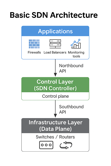
  • SDN Applications: These express the intent or policy that should be enforced in the network — such as load balancing, access control, or routing optimizations.
  • SDN Controller: The brain of the architecture. It receives requests from applications and translates them into instructions for the infrastructure.
  • Network Infrastructure (Data Plane): The physical and virtual switches and routers that forward packets based on the controller's guidance.

Control Plane vs. Data Plane

Traditionally, the control plane and data plane are housed within each device — every switch and router maintains its own forwarding decisions. SDN breaks this pattern. The control logic is extracted and centralized, which simplifies policy enforcement and increases network agility.

Southbound and Northbound APIs

Communication in SDN is mediated by APIs:

  • Southbound APIs: These connect the controller to the forwarding devices. OpenFlow is the leading standard here in 2013.
  • Northbound APIs: These enable SDN applications to program the controller. Though not yet standardized, RESTful APIs are becoming common.

OpenFlow: The Leading Protocol

OpenFlow allows the controller to interact directly with the forwarding plane of switches and routers. It enables dynamic traffic management and offers fine-grained control over packet flows. In 2013, vendors like HP, NEC, Brocade, and Big Switch are shipping OpenFlow-compatible hardware.

Illustrative Architecture

SDN Architecture Diagram

Virtualization and SDN

Server virtualization has become ubiquitous in data centers. SDN extends this flexibility to the network layer. Solutions like VMware NSX and Open vSwitch (OVS) illustrate how SDN supports network abstraction in virtualized environments. This is key for VM mobility, multi-tenancy, and dynamic service chaining.

SDN Controllers

Controllers vary in design. Some are distributed (e.g., ONOS, Floodlight), others centralized (NOX, Beacon). Key capabilities include topology discovery, flow management, path computation, and failover. Most are open-source and programmable via Java, Python, or REST APIs.

Application Scenarios

  • Data Center Automation: Automate network provisioning alongside virtual machine spin-up.
  • Policy Enforcement: Apply consistent access controls across dynamic environments.
  • WAN Optimization: Steer traffic based on application type or performance requirements.

Security Implications

Centralizing control logic introduces new attack surfaces. If the controller is compromised, so is the network. Design strategies must include redundancy, TLS encryption, access controls, and monitoring of API interactions. Defense in depth is non-negotiable in SDN environments.

Challenges in 2013

  • Controller Performance: Can one controller manage large-scale traffic in real-time?
  • Hybrid Deployments: Mixing SDN and traditional networks raises operational complexities.
  • Northbound API Standardization: Lack of uniformity hinders application portability.

Industry Ecosystem and Progress

The Open Networking Foundation (ONF) has accelerated momentum around SDN standards, particularly OpenFlow. Meanwhile, Cisco’s ONE and Juniper’s Contrail demonstrate vendor-specific SDN architectures. The community is growing fast — startups, open-source initiatives, and traditional vendors are investing heavily.

Design Considerations and Future Proofing

Architects evaluating SDN should weigh:

  • Controller placement and redundancy strategies
  • Interoperability with legacy protocols (e.g., BGP, STP)
  • Tooling for orchestration and monitoring (e.g., Puppet, Chef)
  • Scalability of southbound connections (10K+ flows/sec)

Conclusion: Foundational But Evolving

SDN introduces fundamental changes in how we think about networking. This post covered the architectural pillars and operational motivations. In Part 2, we explore real-world deployments, controller platforms, and the growing vendor ecosystem surrounding SDN.


Eduardo Wnorowski is a network infrastructure consultant and Director.
With over 18 years of experience in IT and consulting, he designs high-performance network environments that align with business agility, security, and scalability goals.
Linkedin Profile

Wednesday, May 1, 2013

Optimal STP Design in Multivendor Enterprise Networks

May 2013 • Reading time: 8–10 minutes

As enterprise networks continue to expand and evolve, maintaining a resilient Layer 2 topology across multiple vendors becomes more complex. The Spanning Tree Protocol (STP), while long-standing in its purpose, still requires nuanced design decisions to ensure performance, convergence, and stability in multivendor environments.

The Importance of STP in Multivendor Topologies

Despite newer technologies, STP remains a fundamental part of many enterprise access and distribution layers. Vendors like Cisco, HP, Juniper, and others often implement their own default timers or extensions (such as PVST+, MSTP, or RSTP). This diversity can introduce risks if network engineers aren't deliberate in aligning configurations and behaviors.

Design Challenges and Common Pitfalls

  • Inconsistent default settings: Each vendor ships with different BPDU handling and timer values. Relying on defaults is a recipe for loops or suboptimal failover paths.
  • Root bridge placement: Without intentional placement, spanning-tree root roles may float between platforms, creating unpredictable paths or failovers.
  • Unidirectional link detection: Not all vendors support UDLD. This increases the risk of undetected one-way communication and loops.
  • BPDU Guard and Filter: These safety features are often called by different names, and their misconfiguration may isolate entire access layers.

Designing a Stable STP Foundation

Start by choosing the appropriate STP variant. For environments with Cisco Catalyst and HP ProCurve, RSTP (IEEE 802.1w) is often the common denominator, offering fast convergence while maintaining broad compatibility.

Key configuration practices:

  • Manually assign priority values to root and secondary bridges across all VLANs or instances.
  • Enable BPDU Guard and Root Guard on access ports, especially those facing user devices or unmanaged switches.
  • Set portfast on access ports to accelerate convergence and reduce client-side delays during reboots.
  • Align timers (hello, max age, forward delay) across all switches, avoiding vendor default mismatches.

Monitoring and Troubleshooting Tips

Consistency and documentation are your best tools. Use LLDP/CDP to map inter-switch links and confirm expected STP roles. Enable STP logging and consider SNMP traps for topology changes.

Sample Cisco command to monitor STP on a switch:

Switch# show spanning-tree vlan 10
VLAN0010
  Spanning tree enabled protocol rstp
  Root ID    Priority    24586
             Address     00e0.b6ff.aaaa
             Cost        19
             Port        1 (FastEthernet0/1)
  Bridge ID  Priority    32778
             Address     00e0.b6ff.bbbb
             Hello Time  2 sec  Max Age 20 sec  Forward Delay 15 sec
  Interface           Role Sts Cost      Prio.Nbr Type
  ------------------- ---- --- --------- -------- --------------------------------
  FastEthernet0/1     Root FWD 19        128.1    P2p
  FastEthernet0/2     Desg FWD 19        128.2    P2p
  

Document and Validate the Design

Once designed and implemented, validate your STP design under failure scenarios. Physically unplug uplinks, test redundant paths, and verify logs. Document all expected root roles, blocking ports, and VLAN mappings.

In multivendor networks, STP remains a cornerstone of access and distribution layer design. With deliberate configuration, monitoring, and documentation, it continues to be a resilient foundation in 2013's enterprise environments.


Eduardo Wnorowski is a network infrastructure consultant and technologist.
With over 18 years of experience in IT and consulting, he brings deep expertise in networking, security, infrastructure, and transformation.
Connect on Linkedin

Monday, April 1, 2013

IPv6 Transition Mechanisms and Dual-Stack Enterprise Strategies

April 2013   |   Reading time: ~9 minutes

The transition from IPv4 to IPv6 is one of the most important evolutions in modern networking. In 2013, while IPv6 was already standardized and supported by most platforms, real-world deployment remained a challenge for many enterprise networks. This post explores the available IPv6 transition mechanisms and how dual-stack strategies allow organizations to prepare their infrastructure for a seamless transition.

Understanding the Need for IPv6

IPv4 exhaustion had become more than theoretical by 2011, and regional internet registries were running out of available public IPv4 addresses. IPv6, with its massive 128-bit address space, provides not just more addresses but also improvements in routing, autoconfiguration, and network efficiency.

Common Transition Mechanisms

To ensure compatibility during the transition phase, several mechanisms were developed. These include:

  • Dual-Stack: The device runs both IPv4 and IPv6 simultaneously. This is the most robust and preferred method, particularly for enterprises.
  • Tunneling (6to4, ISATAP, Teredo): These mechanisms encapsulate IPv6 packets within IPv4, allowing IPv6 to traverse legacy infrastructure.
  • Translation (NAT64/DNS64): Allows IPv6-only devices to access IPv4 services.

Implementing Dual-Stack in the Enterprise

Deploying dual-stack involves careful planning. Routers, switches, firewalls, and endpoints must all be configured with both IPv4 and IPv6. DNS infrastructure should support AAAA records, and applications must be tested for IPv6 compatibility.

In Cisco IOS, enabling dual-stack on an interface typically involves:

interface GigabitEthernet0/1
  ip address 192.168.1.1 255.255.255.0
  ipv6 address 2001:db8:abcd::1/64
  no shutdown
  

Challenges and Considerations

Enterprises face several challenges when deploying IPv6:

  • Security Policy Updates: Firewalls and IDS/IPS systems need rules for IPv6 traffic.
  • Monitoring and Logging: Tools must be updated to support IPv6 visibility.
  • Application Readiness: Legacy apps may need refactoring or dual-stack proxies.

Recommended Strategy for 2013

Given the state of IPv6 adoption in 2013, the best path forward for most organizations is to enable dual-stack in internal environments first. Then, extend IPv6 to the DMZ and edge. Careful use of tunneling may help with connectivity testing, but it's not suitable as a long-term solution for production.

Final Thoughts

IPv6 is no longer optional for growing networks. With continued adoption by ISPs and cloud providers, enterprises must ensure their infrastructure and policies are ready. A dual-stack approach offers the most flexibility and least risk during this critical transition period.


Eduardo Wnorowski is a network infrastructure consultant and technologist.
With over 18 years of experience in IT and consulting, he brings deep expertise in networking, security, infrastructure, and transformation.
Connect on Linkedin

Friday, March 1, 2013

Designing Enterprise WAN Architectures with BGP and Path Control

March 2013 | Reading time: 8 minutes

Understanding the Role of BGP in Enterprise WANs

Border Gateway Protocol (BGP) has long been the cornerstone of internet routing, but in recent years it has gained popularity within enterprise WAN environments as organizations aim to enhance resilience, control, and performance. For large enterprises with multiple sites, leveraging BGP allows granular control of traffic paths, prioritization policies, and redundancy models that exceed the capabilities of simpler protocols like OSPF or static routing.

In a traditional enterprise, multiple MPLS circuits or hybrid MPLS-Internet designs require precise outbound and inbound route engineering. BGP's policy-based model is uniquely suited for this, enabling enterprises to influence route selection through attributes such as Local Preference, MED, and AS Path prepending.

Route Maps and Policy-Based Routing

When designing a WAN using BGP, control is paramount. Route maps become one of the most powerful tools available for matching prefixes, applying actions, and filtering routes based on custom logic. For example, an enterprise might define a route map that sets a higher Local Preference for traffic destined to critical SaaS providers, ensuring those flows prefer the MPLS path while general internet access uses broadband backup links.

Policy-Based Routing (PBR) adds another layer of decision-making by enabling forwarding decisions based on source/destination, application type, or even time-of-day. While BGP controls path advertisement and selection, PBR defines how specific traffic types are forwarded regardless of the routing table—ideal for exception-based scenarios like VoIP or backup replication traffic.

Key Design Considerations

  • Redundancy: Ensure dual-homing to multiple ISPs or MPLS providers, with health-checked failover mechanisms using BFD or IP SLA.
  • Prefix Aggregation: Use summarization to reduce the routing table size and improve convergence times.
  • Loop Prevention: In iBGP scenarios, implement full mesh or route reflectors to maintain consistency.
  • AS Path Manipulation: Use AS Path prepending to influence upstream route preferences during failover.
  • Routing Security: Filter inbound routes using prefix-lists and implement MD5 authentication for BGP peers.

Sample BGP Configuration Snippet

router bgp 65000
 bgp log-neighbor-changes
 neighbor 192.0.2.1 remote-as 65010
 neighbor 192.0.2.1 description MPLS-ISP
 neighbor 192.0.2.1 password secureBGP

 address-family ipv4
  network 10.10.0.0 mask 255.255.0.0
  neighbor 192.0.2.1 activate
  neighbor 192.0.2.1 route-map PREFER_MPLS out
 exit-address-family

route-map PREFER_MPLS permit 10
 match ip address prefix-list CRITICAL_ROUTES
 set local-preference 200

Conclusion

Designing enterprise WANs with BGP opens the door to powerful traffic control and failover capabilities. However, success lies in a balanced application of policy, redundancy, and best practices. BGP is not a plug-and-play protocol—without proper route filtering and visibility, route leaks or instability may arise. A carefully structured BGP design that includes route maps, prefix lists, and path manipulation techniques ensures predictable behavior and operational clarity.


Eduardo Wnorowski is a network infrastructure consultant and technologist.
With over 18 years of experience in IT and consulting, he brings deep expertise in networking, security, infrastructure, and transformation.
Connect on Linkedin

Friday, February 1, 2013

Scalable Multicast Design with PIM Sparse Mode and RP Placement

February 2013    ⏱️ 7 min read

As enterprise networks continue to scale, multicast traffic has become a key component for efficient bandwidth usage, particularly in applications like video conferencing, software distribution, and real-time data feeds. In this post, we explore how Protocol Independent Multicast Sparse Mode (PIM-SM) works in large-scale designs, and how strategic Rendezvous Point (RP) placement enhances scalability and reliability.

Understanding PIM Sparse Mode

PIM Sparse Mode is designed for scenarios where multicast receivers are relatively sparse in the network. Instead of flooding multicast traffic, PIM-SM uses an explicit join mechanism where routers signal their interest in specific multicast groups via Join messages.

In PIM-SM, traffic initially flows through a central Rendezvous Point. Sources register with the RP, and receivers send joins toward the RP. Once data starts flowing, routers may optimize the path using Shortest Path Trees (SPT), reducing latency and load on the RP.

Why RP Placement Matters

Incorrect RP placement can lead to suboptimal routing, unnecessary delays, or even data loss in certain failover scenarios. In large networks, placing a single RP can become a bottleneck or single point of failure. Hence, RP design must consider:

  • Proximity to receivers and sources
  • Redundancy and failover capability
  • Protocol support for dynamic election (e.g., Auto-RP or BSR)
  • Stability under high churn

RP Redundancy and Anycast RP

One of the most reliable strategies is using Anycast RP with MSDP (Multicast Source Discovery Protocol). Multiple routers share the same RP address, and MSDP syncs source information among them. This setup provides redundancy and load distribution, enhancing high availability.

To implement Anycast RP, configure identical loopback IPs on multiple routers and advertise them via an IGP. MSDP is then used to replicate source-active messages between the RPs. This ensures that multicast sources are reachable regardless of which RP receives the initial registration.

Design Considerations for Scaling

When planning multicast for scale, consider these best practices:

  • Use Sparse Mode for bandwidth efficiency
  • Strategically place RPs close to the multicast sources or receivers
  • Deploy RP redundancy using Anycast RP + MSDP
  • Ensure IGP convergence is tight to support quick failover
  • Limit multicast scope with TTL boundaries or administrative scoping

Sample Cisco Configuration

interface Loopback0
 ip address 192.168.100.1 255.255.255.255

router ospf 1
 network 192.168.100.1 0.0.0.0 area 0

ip pim rp-address 192.168.100.1

ip msdp peer 192.168.100.2 connect-source Loopback0
  

This configuration sets up a loopback RP and MSDP peering to another router with the same Anycast RP address. The OSPF advertisement ensures reachability within the network core.

Monitoring and Troubleshooting

Tools like show ip pim rp mapping, show ip msdp, and show ip mroute provide valuable visibility into multicast operations. Regularly validate RP status, MSDP peer health, and multicast distribution trees to ensure network stability.

Also consider SNMP or NetFlow-based visibility tools for real-time analysis and proactive alerting in case of RP failures or anomalous multicast traffic.

Conclusion

Multicast continues to be a crucial tool for bandwidth-efficient distribution of real-time data. A solid design based on PIM Sparse Mode, with well-placed and redundant RPs, ensures that even large-scale environments remain scalable and resilient. By integrating dynamic protocols like MSDP and focusing on convergence and visibility, network architects can deliver robust multicast solutions that stand the test of time.


Eduardo Wnorowski is a network infrastructure consultant and technologist.
With over 18 years of experience in IT and consulting, he brings deep expertise in networking, security, infrastructure, and transformation.
Connect on Linkedin

Tuesday, January 1, 2013

High Availability for Internet Edge Designs with VRRP and HSRP

January 2013 - Reading Time: 7 min

Designing a robust and highly available internet edge is a core requirement for enterprise networks in 2013. With increasing reliance on SaaS applications and externally hosted services, downtime at the perimeter can have catastrophic implications. In this article, we explore the strategic deployment of first-hop redundancy protocols — namely VRRP and HSRP — to achieve resilience at the internet edge.

Understanding the Internet Edge

The internet edge typically includes redundant ISPs, firewalls, and border routers. The goal is to maintain connectivity even in the face of hardware failure or a provider outage. However, one of the trickiest components is the gateway IP used by internal hosts or firewalls to reach the outside world. If that gateway IP is tied to a single router, failure of that device results in loss of outbound connectivity.

Introducing VRRP and HSRP

Virtual Router Redundancy Protocol (VRRP) and Hot Standby Router Protocol (HSRP) are designed to solve this problem. Both allow a group of routers to present a virtual IP address as the default gateway. One router is active at any given time, while others remain on standby, ready to take over if the active router becomes unavailable.

HSRP Configuration Overview

HSRP is Cisco proprietary and widely deployed in Cisco environments. Here's a sample configuration for HSRP on two routers sharing the 10.1.1.1 virtual gateway:

interface GigabitEthernet0/0
 ip address 10.1.1.2 255.255.255.0
 standby 1 ip 10.1.1.1
 standby 1 priority 110
 standby 1 preempt
 standby 1 authentication md5 key-string securekey
  

The other router would use a priority of 100, acting as the standby. The preempt command ensures the higher priority router reclaims the active role when it comes back online.

VRRP Configuration Overview

VRRP is an open standard (RFC 5798) and functions similarly. A basic configuration on an interface might look like:

interface GigabitEthernet0/0
 ip address 10.1.1.3 255.255.255.0
 vrrp 1 ip 10.1.1.1
 vrrp 1 priority 120
 vrrp 1 preempt
  

Again, other routers in the group will assume control of the virtual IP if the master fails.

Deployment Tips

  • Ensure proper interface tracking to adjust priority when WAN links fail.
  • Use authentication to prevent rogue devices from joining the redundancy group.
  • Test failover scenarios during maintenance windows to validate behavior.
  • In multi-VLAN environments, configure HSRP/VRRP for each subnet as needed.

Design Considerations

When deploying redundant internet paths, it’s essential to think beyond the routers. Firewalls, WAN optimizers, and load balancers should also support high availability. Consider using asymmetric routing detection and NAT reflection techniques to accommodate failovers cleanly. In more complex setups, dynamic routing protocols like BGP can be integrated with HSRP/VRRP to automate failover based on upstream reachability.

Final Thoughts

In 2013, business continuity demands that enterprises eliminate single points of failure at the network edge. HSRP and VRRP remain essential building blocks in high availability architectures. Whether you’re designing for a small business or a multinational enterprise, redundancy at the gateway level is an investment that pays off in uptime and reliability.


Eduardo Wnorowski is a network infrastructure consultant and technologist.
With over 18 years of experience in IT and consulting, he brings deep expertise in networking, security, infrastructure, and transformation.
Connect on Linkedin

AI-Augmented Network Management: Architecture Shifts in 2025

August, 2025 · 9 min read As enterprises grapple with increasingly complex network topologies and operational environments, 2025 mar...