Tuesday, December 1, 2015

Deploying Site-to-Site VPNs: A Real-World Look at IPsec Tunnels

December 2015    8 min read

Site-to-site Virtual Private Networks (VPNs) based on IPsec have long been a core component of inter-office communication, especially in multi-branch enterprises or companies that need to securely connect data centers. In 2015, many IT teams sought to move beyond legacy frame relay and MPLS solutions to more agile, cost-effective VPN tunnels—most commonly using IPsec.

This post explores the real-world planning, deployment, and performance tuning involved in setting up IPsec tunnels for site-to-site communication. We’ll break down design considerations, routing integration, and a few hard-learned lessons from field deployments.

Understanding the Role of IPsec

IPsec, or Internet Protocol Security, is a suite of protocols that authenticates and encrypts data packets at the IP layer. It provides confidentiality, integrity, and authentication for data in transit. When deploying site-to-site VPNs, IPsec typically operates in tunnel mode, encapsulating the entire IP packet and sending it through a secure tunnel.

Planning the Architecture

The first step in deploying a site-to-site VPN is determining the topology and endpoints. Are you creating a hub-and-spoke design, or a full mesh? Will each site have redundant gateways? Are you connecting across the public Internet, or a hybrid network?

  • Hub-and-Spoke: Centralized control, easier routing.
  • Full Mesh: Higher redundancy, but more complex configuration.
  • Dual WAN Paths: Allows failover between ISPs using IP SLA or similar routing checks.

Plan out subnets to avoid overlap, define tunnel IP ranges if needed, and decide on NAT traversal requirements. Each site should have clearly segmented networks and access control definitions.

Device and Protocol Compatibility

Make sure your edge devices—typically firewalls or routers—support IPsec standards and have compatible encryption algorithms. Inconsistent settings like mismatched DH groups, lifetimes, or encryption suites (AES-256, SHA-2, etc.) are a leading cause of failed tunnel negotiation.

For example, Cisco ASA, Fortinet, Juniper SRX, and even Linux-based strongSwan can interoperate if configurations match exactly.

Routing: Static vs Dynamic

Routing is where many VPN deployments hit roadblocks. You can choose static routes—easy for simple topologies—or dynamic routing protocols like OSPF or BGP to advertise networks between sites.

In 2015, many organizations began using BGP for its granular route control and failover capabilities. When used with IPsec, BGP allows seamless multi-path awareness and can support WAN optimization overlays.

Firewall and ACL Policies

Ensure that firewalls allow ISAKMP (UDP 500), IPsec ESP (protocol 50), and NAT-T (UDP 4500) traffic. ACLs should be precise—permit the traffic needed across the tunnel and nothing more. Remember that IPsec is not inherently restrictive once the tunnel is up. Security must be layered.

Troubleshooting and Verification

Use commands like show crypto isakmp sa, debug crypto ikev1, or tools like Wireshark to verify negotiation and tunnel stability. Log correlation across both endpoints is critical.

Common errors include:

  • Phase 1 mismatch (policy or pre-shared key)
  • Phase 2 mismatch (encryption domains)
  • Routing conflicts or black holes
  • Firewall drops or NAT traversal failures

Performance Considerations

IPsec encryption adds CPU overhead, especially on older firewalls. Ensure hardware acceleration is enabled or offload to dedicated VPN modules. Also, consider MTU/MSS adjustments to prevent fragmentation issues. A common fix is lowering TCP MSS to 1350 bytes on tunnel interfaces.

Best Practices Recap

  • Pre-plan address schemes and tunnel design
  • Use consistent, supported encryption standards
  • Choose appropriate routing protocols
  • Layer firewall policies with access control
  • Log and monitor all phases of tunnel behavior
  • Test failover and redundancy paths

Site-to-site IPsec VPNs remain a reliable and secure method for linking distributed networks when deployed correctly. As with any infrastructure project, the success lies in design discipline and continuous validation.

Eduardo Wnorowski is a network infrastructure consultant and Director.
With over 20 years of experience in IT and consulting, he designs secure environments that scale with business needs and compliance frameworks.
Connect on Linkedin

Sunday, November 1, 2015

EIGRP in Enterprise Networks: Practical Use Cases and Configuration

November 2015  |  9 min read

In the landscape of enterprise networking, routing protocols play a pivotal role in determining network performance, scalability, and manageability. While OSPF and BGP often dominate large-scale network conversations, Enhanced Interior Gateway Routing Protocol (EIGRP) remains a compelling choice for certain enterprise use cases. Its balance of simplicity, speed, and control makes it suitable for many scenarios — especially when implemented with careful planning and deep understanding.

What is EIGRP?

EIGRP is a Cisco proprietary advanced distance-vector routing protocol that incorporates elements of link-state protocols. It uses the Diffusing Update Algorithm (DUAL) to achieve rapid convergence, loop-free routing, and support for multiple network layer protocols, including IPv4 and IPv6.

Unlike RIP, which uses simple hop count metrics, EIGRP calculates its metric based on bandwidth, delay, reliability, and load, offering a more refined and performance-aware route selection mechanism.

Advantages of EIGRP in the Enterprise

  • Rapid convergence: Thanks to DUAL, EIGRP can adapt quickly to topology changes without triggering instability.
  • Load balancing: Supports unequal-cost load balancing with the variance command, offering flexibility in WAN designs.
  • Simplicity: Straightforward to deploy in environments where Cisco gear predominates and extensive interoperability isn’t required.
  • Low overhead: Compared to OSPF, EIGRP produces less control traffic under normal conditions, reducing CPU and bandwidth use on routers.

Practical Use Cases

EIGRP continues to be deployed in a number of real-world situations. Below are a few key use cases where it can shine:

1. Hub-and-Spoke WAN Designs

In designs where a central office connects to many branches via private links (MPLS or leased lines), EIGRP’s summarization and route filtering capabilities provide robust control. Summarization helps reduce routing table size and control plane churn, while filtering allows policy-based route management.

2. Migration Scenarios

Organizations transitioning from static routing or RIP to more modern dynamic routing often use EIGRP as an intermediate step. It provides faster convergence than RIP without the complexity of OSPF area design or BGP policies.

3. Campus Core-to-Distribution Routing

In large enterprise campus designs where modularity is required but full OSPF or BGP might be overkill, EIGRP between the core and distribution layers offers a clean, fast-converging model with support for route summarization and traffic engineering.

Basic Configuration Example

   router eigrp 100
    network 10.0.0.0
    network 192.168.1.0
    no auto-summary
  

This configuration assumes EIGRP AS number 100 and includes two IP ranges. The no auto-summary directive disables automatic classful summarization, allowing for precise subnet advertisements.

Tuning EIGRP for Performance

EIGRP allows tuning of several parameters:

  • Bandwidth and delay: Affect route metrics. These can be adjusted using the bandwidth and delay interface commands.
  • Passive interfaces: Prevent EIGRP from sending updates on interfaces where neighbors should not form (e.g., user VLANs).
  • Timers: hello and hold timers affect neighbor relationships and should be set carefully in WAN environments.

Scaling Considerations

While EIGRP works well in medium-sized networks, scale can become a concern. Proper use of summarization, route filtering, and stub routers helps maintain routing table efficiency and control convergence boundaries. Additionally, EIGRP Stub Routing reduces the amount of routing information exchanged with branches that do not need full topology knowledge.

Interoperability with Other Protocols

One common challenge is the integration of EIGRP with OSPF or BGP at organizational boundaries. Route redistribution must be handled with care, particularly with route-maps and tagging to prevent loops and ensure metric consistency. The use of administrative distance helps control route preference when multiple protocols advertise the same prefixes.

Is EIGRP Still Relevant?

While not open-standard like OSPF or as globally scalable as BGP, EIGRP remains relevant in environments where Cisco is the predominant vendor, interoperability is not a requirement, and simplicity is a virtue. With the advent of EIGRP for IPv6 and limited support by some other vendors, its scope has widened slightly — though it's still mostly tied to Cisco-only environments.


Eduardo Wnorowski is a network consultant and technologist with deep roots in infrastructure and protocol design. With over 20 years of experience in IT and consulting, he delivers pragmatic solutions to complex network challenges.
Connect on Linkedin

Thursday, October 1, 2015

Understanding Route Reflectors in Large BGP Deployments

October 2015 - Reading time: 9 minutes

In large-scale BGP deployments, route reflectors (RRs) are indispensable for simplifying iBGP mesh complexity. Without them, a full mesh of iBGP sessions between all routers in an autonomous system would be required, leading to exponential growth in configuration and maintenance.

Why Route Reflectors?

As BGP scales up in large service provider or enterprise networks, managing full mesh iBGP becomes impractical. Route Reflectors allow certain routers to reflect BGP routes to clients, reducing the number of peerings required.

Unlike confederations, RRs operate within a single AS and maintain simplicity in deployment. They can significantly reduce the control plane load when designed carefully.

Basic Operation

A Route Reflector receives routes from one client and reflects them to other clients or non-clients. It adds a CLUSTER_LIST and ORIGINATOR_ID attribute to track the path and prevent loops. Understanding these mechanisms is crucial to proper RR design.

Designing Route Reflector Topologies

Several design models exist: centralized, hierarchical, and mesh of RRs. Each comes with trade-offs in fault tolerance, convergence speed, and scalability. For instance, centralized RRs are easy to manage but create single points of failure unless redundancy is added.

Best Practices for RR Design

  • Redundancy: Always deploy at least two route reflectors per cluster to avoid single points of failure.
  • Symmetry: Clients should peer with multiple RRs to ensure symmetrical routing and high availability.
  • Load Distribution: Avoid overloading a single RR by balancing client assignments.
  • Loop Prevention: Ensure proper configuration of CLUSTER_IDs and monitoring of CLUSTER_LIST growth.

Common Pitfalls

Misconfiguring cluster IDs or failing to monitor ORIGINATOR_ID propagation can lead to routing loops. Also, reflecting routes across clusters without awareness can introduce unwanted paths.

RRs should never perform policy manipulation without understanding the implications. Excessive route filtering or redistribution can destabilize the iBGP topology.

RR Placement and Hardware Considerations

Though RRs do not forward traffic, their CPU and memory demands can be high in dynamic environments. Choosing the right platform is critical. Software routers with ample resources or control-plane-focused devices often serve as RRs.

Monitoring and Troubleshooting

Use tools like show ip bgp, show ip bgp neighbors, and route analytics platforms to track route reflection behavior. SNMP and telemetry can help identify delays in route propagation or instability.

Logging CLUSTER_LISTs and reviewing ORIGINATOR_IDs can be a powerful troubleshooting method in complex topologies.

Beyond Basics: Advanced Considerations

Operators often deploy route reflectors in MPLS core networks, requiring awareness of label distribution protocols. Additionally, designs using multi-level RR topologies introduce latency and complexity but are necessary at scale.

In data centers or overlay networks, RRs also play roles in BGP EVPN, where route reflection must interact properly with VXLAN and MAC address propagation mechanisms.

Conclusion

Route reflectors are not just an optimization—they are an architectural necessity in large BGP networks. Proper design, monitoring, and policy management ensure scalability and stability. As with any BGP deployment, clear documentation and lab validation are key to long-term success.


Eduardo Wnorowski
With over 20 years of experience in IT and consulting, he brings deep expertise in networking, security, and infrastructure. Eduardo helps businesses scale their network operations with robust design practices and real-world knowledge.
LinkedIn Profile

Tuesday, September 1, 2015

BGP Scalability: Tips and Design Considerations

September 2015 – ⏱️ 9 min read

Border Gateway Protocol (BGP) is the backbone of the internet and many large-scale enterprise networks. As organizations grow, ensuring that BGP scales efficiently becomes a critical aspect of network design. In this post, we’ll explore strategies to optimize BGP scalability while maintaining robustness and control.

Why BGP Scalability Matters

BGP enables inter-domain routing, making it fundamental for ISPs, data centers, and large enterprises. Poorly designed BGP implementations can lead to route flaps, memory exhaustion, and routing convergence delays—resulting in service instability and outages.

1. Prefix Aggregation

One of the simplest yet most effective ways to reduce BGP table size is through prefix aggregation. Summarizing multiple routes into fewer advertisements decreases the memory and CPU demands on BGP routers. Route summarization is particularly critical at redistribution points between IGPs and BGP.

2. Route Reflectors vs Full Mesh

iBGP requires a full mesh by default, which does not scale well. Introducing route reflectors (RRs) simplifies topology by allowing iBGP speakers to reflect routes to clients. However, designers must ensure RRs are placed strategically and are redundant to avoid single points of failure.

3. Peer Grouping and Template Use

Configuring peer groups or session templates in BGP significantly reduces the complexity and CPU overhead in managing large numbers of peers. This also reduces the amount of configuration required, making operational management easier.

4. Control Plane Resource Management

Scalable BGP design requires proper CPU and memory allocation. Control plane policing (CoPP) should be implemented to prevent routing protocol starvation during DDoS attacks. Modern hardware with separation of control and forwarding planes is ideal.

5. Route Filtering and Policies

Implementing inbound and outbound route filters limits the number of accepted routes and prevents the advertisement of unnecessary or harmful prefixes. Tools like prefix-lists, route-maps, and policy-based routing are instrumental in maintaining routing hygiene.

6. BGP Confederations

BGP confederations divide an AS into sub-ASes to reduce iBGP mesh complexity. Confederations are particularly useful in very large enterprise or provider networks with multiple routing domains. However, they add a layer of abstraction that must be carefully documented and understood.

7. Route Dampening

Route dampening helps mitigate the impact of route flapping by penalizing unstable routes. It’s a double-edged sword: improperly tuned dampening can suppress legitimate updates. It should be used selectively, primarily for routes known to flap.

8. Graceful Restart and NSF

To minimize routing disruption during control plane restarts, features like Graceful Restart and Non-Stop Forwarding (NSF) are essential. These mechanisms allow data plane continuity while control plane recovers, preserving service stability.

9. Monitoring and Visibility

Scalability isn’t just about initial design—it’s also about ongoing operations. Tools like BGP-LS, BMP (BGP Monitoring Protocol), and telemetry solutions provide vital insights into routing behavior. Anomalies can be detected early and investigated thoroughly.

10. Testing and Lab Validation

Before deploying BGP design changes into production, thorough validation in a lab environment is critical. Emulate realistic route loads, simulate failures, and measure convergence behavior. Consider using emulation tools like GNS3, EVE-NG, or vendor-specific virtual labs.

Scalable BGP architecture is a balance between performance, control, and simplicity. With careful design and active monitoring, networks can accommodate growth without compromising stability.


Eduardo Wnorowski is a network infrastructure consultant and Director. With over 20 years of experience in IT and consulting, he designs scalable network architectures that support growing enterprise demands with efficiency and reliability.
Connect on Linkedin

Saturday, August 1, 2015

BGP Attributes: Path Control and Policy Enforcement in Enterprise Networks

 August 2015 | 6 min read

Introduction

BGP (Border Gateway Protocol) plays a foundational role in modern enterprise network design, particularly in multi-site environments where policy-based routing and path optimization are critical. In the early days of networking, static routing and simple IGPs like OSPF or EIGRP sufficed for internal path determination. However, the complexity of today's enterprise WANs—with multiple internet uplinks, cloud interconnects, MPLS, and hybrid SD-WAN overlays—demands a more sophisticated control plane. This is where BGP excels.

Despite its origins as an exterior routing protocol, BGP's flexibility and rich attribute system allow it to be deployed internally (iBGP) to enforce granular path selection and traffic engineering policies. This article unpacks the key BGP attributes that influence path control and explores how they can be harnessed in enterprise scenarios to meet business and technical requirements.

BGP Attributes Overview

At the heart of BGP's decision-making process lies its attribute-based path evaluation system. Each route received via BGP is associated with a set of attributes that influence the best path selection. Some attributes are well-known and mandatory; others are optional or transitive, allowing custom behavior across autonomous systems.

The most commonly used attributes in enterprise routing are:

  • Weight: Cisco proprietary and local to the router. Highest weight wins.
  • Local Preference: Used within an AS to prefer exit points; higher is better.
  • AS-Path: Shorter paths are preferred. Useful for loop prevention and basic routing policy.
  • Origin: Preference is IGP > EGP > Incomplete.
  • MED (Multi-Exit Discriminator): Suggests preferred entry points to neighboring ASes; lower is better.
  • Community and Extended Community: Tags to apply policies across route-maps and peer groups.

These attributes form the foundation of route manipulation strategies. They can be set or filtered using route-maps, prefix-lists, and policy-based routing statements.

Path Selection Mechanisms

Once BGP has collected multiple paths to the same destination prefix, it must determine the best route to install in the RIB (Routing Information Base). The BGP decision process is deterministic and follows a predefined sequence of attribute comparisons. This hierarchy is crucial to understand when implementing policy.

  1. Prefer the path with the highest Weight
  2. If equal, prefer the highest Local Preference
  3. If equal, prefer routes originated by the local router (originated via network or aggregate)
  4. Prefer the shortest AS Path
  5. Prefer the lowest Origin code (IGP < EGP < Incomplete)
  6. Prefer the lowest MED (if paths are from the same AS)
  7. Prefer eBGP over iBGP routes
  8. Prefer the path with the lowest IGP metric to the BGP next hop
  9. Prefer the oldest route (to promote stability)
  10. Prefer the path with the lowest router ID

This sequence ensures consistent behavior, but it can be altered using policy tools like route-maps, where administrators inject logic to override natural decisions based on business constraints, application performance, or link costs.

Policy Enforcement Strategies

BGP's real strength is in its ability to enforce policy at various points in the network. For instance, an enterprise might wish to prefer MPLS for VoIP traffic, but prefer DIA (Direct Internet Access) for cloud SaaS like Office 365. BGP can implement such logic by setting communities and local-preference tags at ingress points, then adjusting outbound decisions accordingly.

Key tools include:

  • Route-maps: Act as conditional logic gates, permitting or modifying routes based on ACLs, prefix-lists, or communities.
  • Prefix-lists: Fine-grained match filters for route announcements.
  • Community tagging: A scalable way to label routes for downstream processing.
  • Policy-based routing: Allows forwarding decisions based on fields like source IP or DSCP, outside of normal destination-based routing.

These tools allow enterprises to model policy that reflects business structure: preferring cheaper bandwidth for non-critical data, segmenting traffic flows per department, or engineering failover paths that meet SLA thresholds.

Enterprise Use Cases

Several real-world use cases highlight the power of BGP path control:

  • Dual WAN Uplink: Enterprises with both MPLS and Internet connections can use local-pref and communities to route critical traffic over MPLS and bulk traffic over broadband.
  • Inter-branch Traffic Engineering: Sites connected via multiple service providers can influence inbound path selection by adjusting MED or AS-PATH prepending.
  • Cloud On-Ramp: Enterprises with direct connections to Azure/AWS/GCP can tag routes to prefer the closest PoP (Point of Presence).
  • Redundancy & Failover: BGP timers and route withdrawal behavior can be tuned to speed up convergence in case of WAN failures, combined with static fallback routes as safety nets.

These patterns repeat across industries—whether it's a retail chain, a manufacturing plant with IoT gateways, or a university with hybrid connectivity.

Summary and Recommendations

Understanding BGP attributes and their role in path control is essential for any network engineer tasked with ensuring availability, performance, and policy compliance in modern enterprises. By leveraging tools like local-pref, MED, route-maps, and communities, organizations can design flexible, robust networks that respond to changing demands and operational conditions.

As enterprises continue to adopt SD-WAN and cloud architectures, BGP remains not only relevant but critical for integrating overlay control with underlay infrastructure.


Eduardo Wnorowski is a network infrastructure consultant and technologist.
With over 20 years of experience in IT and consulting, he brings deep expertise in networking, security, infrastructure, and transformation.
Connect on Linkedin

Monday, July 20, 2015

Scaling BGP – Part 3: BGP Confederations in Practice

July 2015   |   Reading Time: 13 minutes

Introduction

BGP Confederations provide a viable solution to scaling BGP within large Autonomous Systems (ASes). In this final post of our deep dive series, we turn to the practical considerations, deployment methodologies, and real-world use cases of BGP Confederations, extending the theory into operational reality.

Recap of BGP Scaling Challenges

As outlined in previous entries, large-scale BGP deployments face issues like excessive iBGP mesh complexity, route processing load, and control plane overhead. Confederations, like Route Reflectors (RRs), attempt to solve these by breaking up the iBGP domain while maintaining exterior BGP behavior.

BGP Confederation Structure in Practice

A BGP Confederation divides a single AS into multiple sub-ASes. These sub-ASes maintain full iBGP within themselves but use eBGP between each other—although configured with a private ASN and treated as part of the parent AS externally.

  • AS_CONFED_SET and AS_CONFED_SEQ: Used to preserve path history between sub-ASes.
  • Local policies: Each sub-AS can apply routing policies for better control.
  • Reduced session load: Fewer iBGP sessions needed overall.

Deployment Methodologies

There is no one-size-fits-all model, but some common patterns include:

1. Regional Sub-AS Design

Split the AS geographically—e.g., Sub-AS 65001 (Europe), 65002 (Asia), 65003 (Americas). This isolates regional changes and failures, helping both with scalability and stability.

2. Functional Sub-AS Design

Divide the AS by function or business unit—for instance, separating backbone, access, and services domains within a large enterprise or ISP.

Configuration Examples

A minimal example to illustrate Confederation setup in Cisco IOS:

    router bgp 65000
     bgp confederation identifier 65000
     bgp confederation peers 65001 65002
     neighbor 192.0.2.1 remote-as 65001
     neighbor 192.0.2.2 remote-as 65002
  

Each sub-AS (e.g., 65001, 65002) will be configured similarly with its own peerings and policies, referencing 65000 as the confederation identifier.

Operational Considerations

  • Visibility: Confederations reduce path visibility, which may affect troubleshooting.
  • Loop Prevention: Sub-ASes must be carefully designed to prevent routing loops.
  • Transition Complexity: Moving from flat iBGP to a confederation model requires careful migration planning.
  • Support: Ensure hardware/software platforms support confederation capabilities fully.

Comparison with Route Reflectors

Both Route Reflectors and Confederations solve the iBGP full-mesh problem, but:

  • RRs are easier to deploy incrementally, but introduce non-determinism in route selection.
  • Confederations offer better policy control but increase AS-level complexity.

Case Study: Large-Scale Provider Backbone

One Tier-1 provider implemented a confederation model with five regional sub-ASes. Each region had internal RRs and operated independently. Policies across sub-AS boundaries enforced service-specific routing paths and helped contain failures within regional scopes.

When to Use Confederations

Confederations are ideal when:

  • You need granular policy control across distinct network domains.
  • The iBGP session scale is too large for RRs alone.
  • Organizational boundaries or M&A activity requires AS segmentation.

Conclusion

BGP Confederations, while more complex than traditional RRs, offer compelling benefits in large-scale AS architectures. When designed and implemented carefully, they enable efficient routing domain segmentation, better policy enforcement, and enhanced control plane scalability.


Eduardo Wnorowski is a network infrastructure consultant and technologist.
With over 20 years of experience in IT and consulting, he helps organizations design scalable network infrastructures using BGP and related protocols.
Linkedin Profile

Wednesday, July 1, 2015

Redistribution Pitfalls: Avoiding Routing Loops and Black Holes

July 2015 - Reading Time: ~9 minutes

Route redistribution can be a powerful technique for connecting different routing domains, protocols, or administrative boundaries. However, when improperly configured, it can introduce severe problems such as routing loops, suboptimal paths, and even black holes that silently drop traffic. This post explores how redistribution works, the risks involved, and techniques to ensure safe, efficient route redistribution in your enterprise network.

What Is Route Redistribution?

Route redistribution allows routes learned by one routing protocol to be advertised into another. This is useful when transitioning from one protocol to another (e.g., EIGRP to OSPF), or when integrating networks acquired during a merger.

Consider a network that uses EIGRP internally but must share connectivity with a provider running OSPF. Redistribution makes this possible—but not without introducing risk. Each protocol calculates metrics differently, lacks awareness of the other's internal topologies, and may create asymmetric paths.

Common Redistribution Scenarios

  • Mutual Redistribution: Injecting routes in both directions (e.g., OSPF ↔ EIGRP)
  • Partial Redistribution: One-way sharing of routes (e.g., static → OSPF)
  • Multiple AS Integration: Combining domains with different protocols during M&A or inter-domain peering

Mutual redistribution, while common, is particularly susceptible to routing loops.

Pitfall 1: Routing Loops

Loops often result when redistributed routes are re-learned and re-advertised in a circular fashion across protocol boundaries. Consider this scenario:

  • Route A exists in EIGRP
  • It is redistributed into OSPF
  • OSPF advertises Route A back into EIGRP (now as external)
  • EIGRP prefers the new external route over the internal, due to metric manipulation or administrative distance

This loop creates instability and traffic misdirection. Without proper filtering and tagging, the router cannot differentiate between the original and redistributed versions of the same route.

Solution: Route Tagging

To prevent loops, apply route tags during redistribution. Tags act as metadata that inform the receiving protocol about the route’s origin.

    router ospf 10
     redistribute eigrp 100 subnets tag 100

    router eigrp 100
     redistribute ospf 10 metric 10000 100 255 1 1500 route-map BLOCK_OSPF_TAG

    route-map BLOCK_OSPF_TAG deny 10
     match tag 100

    route-map BLOCK_OSPF_TAG permit 20
  

In this example, OSPF routes tagged with 100 will be filtered out by EIGRP, preventing re-injection of external routes.

Pitfall 2: Metric Mismatches

Protocols use different metrics: OSPF uses cost, EIGRP uses bandwidth and delay. Without careful planning, redistributed routes may have absurd metrics, causing poor path selection or path flapping.

Solution: Define Metrics Explicitly

Always define metrics during redistribution. Relying on defaults may result in inconsistent behavior or loops. Consider using route-maps to apply metrics and selectively filter undesirable routes.

    router ospf 1
     redistribute eigrp 1 subnets metric-type 1 metric 10
  

Pitfall 3: Subnet Inconsistencies

Redistribution without including subnet information can collapse multiple prefixes into a single advertisement, causing reachability issues or loss of granularity.

Use the subnets keyword to ensure all routes are properly advertised:

    redistribute eigrp 100 subnets
  

Design Best Practices

  • Use route tagging religiously
  • Implement route-maps to control what is redistributed
  • Monitor redistributed routes with logging and route tracking
  • Avoid mutual redistribution unless absolutely necessary
  • Use summarization to reduce route churn

Lab Simulation: OSPF-EIGRP Redistribution

Set up a small lab with two routers: R1 running EIGRP and R2 running OSPF. Connect them via a common interface and configure mutual redistribution. Tag routes from EIGRP with tag 100, then apply a route-map on R2 to block those tagged routes from being redistributed back.

This exercise reinforces tagging and filtering while visualizing how loops may emerge without protection.

Conclusion

Redistribution is not a set-and-forget tool—it demands careful planning, deep understanding of routing behavior, and continuous monitoring. Use route-maps, tagging, metric definition, and thorough testing to protect your network from inadvertent instability. A clean, loop-free redistribution design can make multi-protocol integration seamless and secure.


Eduardo Wnorowski is a network infrastructure consultant and technologist.
With over 20 years of experience in IT and consulting, he brings deep expertise in networking, security, infrastructure, and transformation.
Connect on Linkedin

Monday, June 1, 2015

Demystifying Route Summarization: Techniques for Scalable IP Design

June 2015   |   Reading Time: 10 min read

Introduction

Route summarization is a foundational technique in IP networking that enables efficient routing, minimizes CPU utilization, and reduces the size of routing tables. As networks grow in complexity, summarization becomes a critical tool for scalability and manageability. This post dives deep into summarization strategies, design best practices, and common pitfalls to avoid when aggregating IP routes.

What Is Route Summarization?

Route summarization is the process of aggregating multiple IP prefixes into a single, broader address. Instead of advertising several individual subnets, routers can send a single summary route. This reduces routing overhead and simplifies control plane operations.

Example: Instead of advertising 192.168.1.0/24 through 192.168.4.0/24, you can summarize them as 192.168.0.0/22.

Why Use Route Summarization?

  • Reduces routing table size and improves performance
  • Limits the impact of topology changes
  • Improves convergence speed
  • Reduces routing update traffic
  • Provides better scalability for large networks

Summarization in EIGRP

EIGRP supports manual summarization on a per-interface basis. This provides great control but requires intentional planning.

interface Serial0/0
 ip summary-address eigrp 100 10.0.0.0 255.255.252.0

Be careful not to over-summarize, which may lead to black holes if the summarized range includes unused addresses not routed elsewhere.

Summarization in OSPF

OSPF performs summarization at ABR and ASBR routers only. It is configured using the area range or summary-address commands.

router ospf 1
 area 1 range 10.1.0.0 255.255.0.0

This allows OSPF to advertise a single route to other areas, minimizing LSA flooding.

Route Summarization Techniques

  • Bitwise Comparison: Compare binary representations to find the common prefix.
  • CIDR Alignment: Ensure summary routes align with classless subnet boundaries.
  • Interface-based Control: Apply summary addresses per interface where supported.
  • Hierarchy Design: Design IP addressing to support summarization from the start.

Summarization Calculation Example

You want to summarize these routes:

  • 192.168.16.0/24
  • 192.168.17.0/24
  • 192.168.18.0/24
  • 192.168.19.0/24

All four share the first 22 bits, so the summary is:

192.168.16.0/22

Design Best Practices

  • Plan IP addressing with summarization in mind
  • Use loopback addresses in summaries carefully
  • Avoid overlapping summaries between areas or domains
  • Document each summary range and its coverage
  • Combine summarization with route filtering where needed

Verifying Summarization

  • Use show ip route to inspect summary entries
  • Check show ip protocols for summary advertisement
  • Ping destination subnets to validate reachability
  • Use traceroute to confirm path selection

Common Pitfalls

  • Black holing traffic due to summarizing unallocated space
  • Neglecting to advertise more specific routes for exception handling
  • Failing to coordinate summary ranges across routing domains
  • Incorrect mask calculations resulting in unintended aggregation

Conclusion

Route summarization is more than a space-saving measure—it’s a cornerstone of scalable IP design. When used appropriately, it provides better control, minimizes churn, and reduces routing complexity. Whether you’re designing a core enterprise network or managing distributed branch connectivity, mastering summarization techniques will elevate your routing architecture to the next level.


Eduardo Wnorowski is a network infrastructure consultant and technologist.
With over 20 years of experience in IT and consulting, he brings deep expertise in networking, security, infrastructure, and transformation.
Connect on Linkedin

Wednesday, May 20, 2015

Scaling BGP – Part 2: Design and Implementation of Route Reflectors

May 2015 - Reading Time: 12 minutes

Introduction

In Part 1, we explored the motivations behind scaling BGP in large networks and examined the limitations of a full-mesh iBGP topology. Now we shift our focus to the next phase: designing and implementing Route Reflectors (RRs). Route Reflectors reduce iBGP mesh complexity while preserving path visibility and control—if configured correctly. But the design process comes with challenges that impact convergence, redundancy, and policy enforcement.

What Is a Route Reflector?

A Route Reflector is a BGP router that can reflect routes learned from one iBGP peer (client) to another. This deviates from the standard iBGP rule that says routers must not advertise iBGP-learned routes to other iBGP peers. The mechanism is defined in RFC 4456.

There are three types of peers in an RR topology:

  • Clients: iBGP neighbors from which the RR learns and to which it reflects routes.
  • Non-Clients: iBGP neighbors of the RR that are not clients—RRs do not reflect routes between them.
  • Other RRs: In large deployments, RRs peer with each other to propagate routes further.

Basic Topologies and Design Variants

Designing an RR topology is not just about picking one or two routers to act as reflectors. It requires careful consideration of failure domains, redundancy, and route availability. The most common approaches include:

1. Single Route Reflector

This is the simplest and least fault-tolerant configuration. All iBGP clients peer with one RR. If the RR fails, the clients are isolated. While not recommended for production, it's still found in labs and small networks.

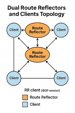
2. Dual Route Reflectors

Two RRs provide redundancy. Clients peer with both. This is more resilient, but comes with new challenges in route consistency. Clients may receive different best paths from each RR, depending on IGP metrics and RR state.

3. Hierarchical Route Reflectors

In very large-scale environments, RRs may be organized in tiers—core, aggregation, and access. Clients peer with local RRs, and RRs peer among themselves in a hierarchical fashion. This enables scalability while limiting the failure domain of any one RR.

4. Confederation + Route Reflectors

In very large ISPs or MPLS VPN deployments, Confederations are combined with RRs for even greater scalability. Each confederation sub-AS may have its own RRs, with inter-sub-AS peering maintained at the border.

iBGP Client Configuration: An Example

Let's take a simple topology with two route reflectors and three clients. Here's a configuration snippet from a Cisco device acting as a client:

router bgp 65000
 bgp log-neighbor-changes
 neighbor 10.0.0.1 remote-as 65000
 neighbor 10.0.0.1 route-reflector-client
 neighbor 10.0.0.2 remote-as 65000
 neighbor 10.0.0.2 route-reflector-client

The 'route-reflector-client' command tells the router that these neighbors can reflect routes to it. On the RR side, the same directive applies for each client peer.

Design Considerations

1. IGP Consistency

RRs select best paths based on BGP attributes and IGP metrics. If your IGP cost to clients varies significantly, your best path may be inconsistent across RRs. Keep the IGP stable and symmetric where possible.

2. BGP Attributes Preservation

By default, RRs do not modify most BGP attributes, but some attributes (like ORIGINATOR_ID and CLUSTER_LIST) are added to prevent loops. Be aware of how these attributes affect downstream policy and selection.

3. Convergence Tradeoffs

Reflectors reduce the number of iBGP sessions but may slow down convergence compared to full mesh. Route withdrawals may propagate more slowly. You may need to tune BGP timers or deploy BGP PIC (Prefix Independent Convergence) for improvement.

4. Cluster-ID Strategy

Each RR cluster must have a unique Cluster-ID to avoid loops. When multiple RRs are deployed in the same cluster, they must share the same Cluster-ID. Mismatches can cause routing blackholes or path inconsistencies.

Testing and Visibility

To validate your RR setup, use the following techniques:

  • Check the BGP table for reflected prefixes using show ip bgp or show bgp ipv4 unicast.
  • Inspect the CLUSTER_LIST and ORIGINATOR_ID fields for path loop prevention.
  • Test route failover scenarios to ensure redundancy behaves as expected.
  • Use traceroute or ping with loose source routing to simulate asymmetric paths.

Operational Pitfalls

Some common issues when deploying RRs include:

  • Clients accidentally configured as non-clients, leading to missing routes
  • Route dampening policies incorrectly applied at the RR, causing route flaps
  • Uneven path selection due to differing IGP metrics or missing MEDs
  • Failure to reflect loopback reachability, breaking next-hop resolution

These can be addressed with a combination of peer-template configurations, strict prefix filtering, and route policies tailored for RR logic.

Visualization

RR Topology Example

Conclusion

Route Reflectors offer a scalable and efficient way to manage iBGP topologies, especially in networks that grow beyond a few dozen routers. However, they are not a silver bullet. Design decisions around redundancy, attribute propagation, and convergence must be deliberate. In Part 3, we’ll explore best practices and performance tuning techniques to optimize your BGP design further.


Eduardo Wnorowski is a network infrastructure consultant and architect.
With over 20 years of experience in IT and consulting, he builds scalable, high-performance environments for enterprise and service provider networks.
Connect on Linkedin

Friday, May 1, 2015

Using Loopback Interfaces Strategically in Network Design

May 2015   |   Reading Time: 10 min read

Introduction

Loopback interfaces are virtual, logical interfaces that are always up as long as the router is operational. While they may seem simple, loopbacks play a critical role in network design. They are used for router identification, testing, routing protocols, and management access. This article explores why and how loopbacks should be used strategically in both enterprise and service provider environments.

What Is a Loopback Interface?

A loopback interface is a software-only interface that doesn’t correspond to any physical port. It cannot go down unless the entire device fails. This stability makes it ideal for identifying routers in a topology.

interface Loopback0
 ip address 192.0.2.1 255.255.255.255

Why Use Loopbacks?

  • Router ID Selection: Most routing protocols use the highest IP address on a loopback interface as the router ID.
  • Stable Next-Hop Addressing: Loopbacks are unaffected by physical link failures.
  • Management Access: SNMP, SSH, and NMS systems rely on consistent loopback IPs.
  • Testing and Monitoring: Loopbacks are ideal for traceroute targets and monitoring paths.

Loopbacks in OSPF

OSPF prefers the highest loopback IP address as the Router ID unless explicitly configured:

router ospf 1
 router-id 192.0.2.1

Advertising a loopback interface into OSPF helps ensure reachability regardless of physical interface status. Use a /32 mask to avoid confusion:

interface Loopback0
 ip address 192.0.2.1 255.255.255.255

Loopbacks in EIGRP

EIGRP can also advertise loopback interfaces. These interfaces should be explicitly included in the EIGRP network command:

router eigrp 100
 network 192.0.2.0 0.0.0.255

Because loopbacks are always up, they’re useful for injecting stable summary routes and for passive interface roles.

Best Practices for Loopbacks

  • Use /32 addresses for clarity and routing consistency.
  • Choose addresses from a globally reachable loopback range.
  • Advertise loopbacks in your IGP to ensure reachability.
  • Use loopbacks as BGP router-IDs and for peering endpoints.
  • Make loopbacks passive in IGPs unless needed for adjacency.

Loopbacks in iBGP and MPLS

In iBGP, loopbacks are used as BGP router IDs and as source/destination addresses for peering sessions. They ensure that BGP sessions are resilient to physical interface changes:

router bgp 65000
 neighbor 192.0.2.2 remote-as 65000
 update-source Loopback0

In MPLS, loopbacks identify LSRs and are used as the target for LDP bindings. Every MPLS-enabled router should have a loopback advertised into the IGP with appropriate reachability.

Verifying Loopback Use

  • Use show ip interface brief to verify the loopback state.
  • Use show ip ospf or show ip eigrp interfaces to confirm loopback inclusion.
  • Use ping and traceroute to test loopback reachability.

Security Considerations

  • Limit access to loopbacks with ACLs or firewall policies.
  • Apply infrastructure protection techniques to block spoofing and DoS attacks targeting loopbacks.
  • Restrict SNMP and SSH access to trusted NMS sources only.

Conclusion

Loopback interfaces are more than a formality—they are foundational elements in a resilient and well-designed IP network. From serving as stable router identifiers to being essential in BGP and MPLS operations, loopbacks provide consistency and robustness. Strategic use of loopbacks improves not only operational visibility but also protocol behavior and security posture. Every network engineer should leverage them effectively in design and deployment.


Eduardo Wnorowski is a network infrastructure consultant and technologist.
With over 20 years of experience in IT and consulting, he brings deep expertise in networking, security, infrastructure, and transformation.
Connect on Linkedin

Wednesday, April 1, 2015

Fine-Tuning EIGRP Metrics: Understanding Bandwidth, Delay, and K Values

April 2015   |   Reading Time: 10 min read

Introduction

Enhanced Interior Gateway Routing Protocol (EIGRP) remains a preferred choice in many enterprise environments for its balance of performance and simplicity. While often praised for its ease of deployment, EIGRP’s true power lies in its customizable metric system. Engineers who understand how bandwidth, delay, and K values interact can influence path selection with surgical precision. This post explores how to fine-tune EIGRP metrics effectively.

EIGRP Metric Formula

EIGRP uses a composite metric that includes bandwidth, delay, reliability, load, and MTU. The default metric calculation uses only bandwidth and delay, and the simplified formula looks like this:

metric = 256 * (K1 * bandwidth + K3 * delay)

By default, K1 and K3 are set to 1, and all other K values (K2, K4, K5) are set to 0. This means that only bandwidth and delay impact the routing decision.

Understanding Bandwidth in EIGRP

EIGRP treats bandwidth as the minimum bandwidth along the path. Lower bandwidth increases the metric and makes a path less preferred.

interface FastEthernet0/1
 bandwidth 10000

Note: This does not limit actual throughput. It's only used for metric calculations and QoS shaping.

Understanding Delay in EIGRP

Delay is cumulative and expressed in tens of microseconds. EIGRP adds the delay of each interface along the path. Lower delay means a better metric.

interface Serial0/0
 delay 2000

Be cautious when manually adjusting delay to influence routing—it impacts convergence and route selection.

Customizing K Values

You can modify which factors EIGRP uses by changing the K values, but this must be consistent across the entire EIGRP domain.

router eigrp 100
 metric weights 0 1 0 1 0 0

This configuration activates bandwidth (K1) and reliability (K4), which is uncommon and can introduce instability if not coordinated.

Why Not Use Reliability or Load?

  • Reliability and load are dynamic and can fluctuate rapidly.
  • Instability in these metrics can cause frequent route recalculations.
  • Best practice is to avoid using K2, K4, and K5 in production unless explicitly required and monitored.

Influencing Routing Decisions

Adjusting interface delay is the safest and most predictable method to influence EIGRP metrics. Use it when you want to prioritize certain links over others without changing topology.

interface Serial0/1
 delay 1500

Metric Calculation Example

Assume a path with two interfaces: one with bandwidth of 100 Mbps and delay of 1000, the other with bandwidth of 10 Mbps and delay of 2000.

metric = 256 * (10^7 / min_bw + sum_delay)

metric = 256 * (10^7 / 10000 + 3000) = 256 * (1000 + 3000) = 1,024,000

Verification and Troubleshooting

  • Use show ip protocols to verify active K values.
  • Use show ip route eigrp to confirm path selections.
  • Use show interfaces to check bandwidth and delay settings.
  • Use debug eigrp fsm for deeper convergence analysis (use cautiously).

Best Practices

  • Stick to default K values unless you have a clear use case.
  • Adjust delay rather than bandwidth to influence metrics.
  • Document any metric manipulations for audit and troubleshooting.
  • Test changes in a lab environment before deploying to production.

Conclusion

Understanding how EIGRP calculates its composite metric gives network engineers a significant degree of control. Whether you're influencing primary paths or preparing for convergence scenarios, knowing when and how to tune bandwidth, delay, and K values can elevate your routing strategy. With great power comes great responsibility—so adjust carefully, document thoroughly, and always test before rollout.


Eduardo Wnorowski is a network infrastructure consultant and technologist.
With over 20 years of experience in IT and consulting, he brings deep expertise in networking, security, infrastructure, and transformation.
Connect on Linkedin

Friday, March 20, 2015

Scaling BGP – Part 1: The Case for BGP Scalability in Large-Scale Networks

March 2015   •   Reading time: 12 minutes

Why BGP Needs to Scale

As enterprises and service providers expand their networks to meet the demands of global users, the Border Gateway Protocol (BGP) faces new challenges. In its original form, BGP wasn't designed for the massive scale it now supports. From sprawling data centers to regional ISPs, the protocol's default mechanisms often strain under the complexity of large-scale topologies.

Today’s post examines the limitations of traditional BGP in modern networks and sets the stage for why scalable mechanisms such as Confederations and Route Reflectors (RRs) have become essential.

Recap: What is BGP?

BGP is a path vector protocol that governs inter-domain routing across the internet. It’s used to exchange routing information between autonomous systems (ASes), providing a framework for routing policy, reachability, and route selection based on attributes such as AS_PATH, MED, LOCAL_PREF, and more.

Although BGP is considered a protocol of last resort due to its manual tuning, it's the backbone of global routing. Within an AS, Interior BGP (iBGP) allows routers to share information internally, which becomes critical as networks grow in size and complexity.

The Problem with Full Mesh iBGP

By default, iBGP requires a full mesh of peerings among all BGP-speaking routers in the same AS. This ensures all routers receive complete routing information, but the scalability limits become apparent quickly.

  • Each router must peer with every other router.
  • This results in n(n-1)/2 sessions, where n is the number of routers.
  • Administrative overhead increases exponentially.
  • Router CPU and memory consumption rises with each additional peer.

In practice, full mesh becomes unmanageable once you surpass even 10–20 routers. This is where hierarchical design becomes necessary.

Case Study: ISP with 75 Core Routers

Imagine an ISP operating with 75 routers across regional cores, border routers, and peering points. A full mesh of 75 iBGP routers would require 2,775 BGP sessions. Maintaining this at scale is not only inefficient—it’s nearly impossible.

Beyond the session count, consider the propagation delays, route processing queues, and convergence complexity. In such environments, full mesh is not viable.

Requirements for Scalable BGP

To scale BGP within an AS, network architects need mechanisms that:

  • Reduce the number of required peerings
  • Maintain loop-free and complete route visibility
  • Support policy control and traffic engineering
  • Ensure fast convergence and fault isolation

Two main solutions have emerged to solve these challenges:

  • Route Reflectors (RRs): A mechanism to centralize iBGP route distribution.
  • Confederations: A way to split a single AS into smaller sub-ASes for iBGP scalability.

Preview: What’s Next in the Series

This post lays the groundwork for the upcoming two parts in this deep dive series:

  1. Part 2: Design and Implementation of Route Reflectors
  2. Part 3: Leveraging BGP Confederations for Hierarchical Control

Each of these scaling techniques comes with its own design considerations, pitfalls, and operational trade-offs. Understanding when and how to use them is critical to maintaining a scalable and robust network.


💡 Pro Tip: Start documenting iBGP peerings and dependencies before implementing Route Reflectors. Visibility is the first step to control. 


Eduardo Wnorowski is a network infrastructure consultant and Director.
With over 20 years of experience in IT and consulting, he designs routing architectures that scale with performance and policy control.
Connect on Linkedin

Sunday, March 1, 2015

Mastering OSPF Stub Areas: When and Why to Use Them

March 2015   |   Reading Time: 10 min read

Introduction

Open Shortest Path First (OSPF) is a link-state routing protocol widely used in enterprise and service provider networks. As OSPF networks scale, it becomes critical to manage the size of routing tables and the number of LSAs (Link-State Advertisements) flooded throughout the topology. OSPF stub areas are one method to reduce this overhead without sacrificing network reachability.

What Are OSPF Stub Areas?

Stub areas are special types of OSPF areas where external routes (Type 5 LSAs) are restricted. Instead of learning each external route individually, routers in stub areas receive a default route (0.0.0.0/0) pointing toward the ABR (Area Border Router).

Types of Stub Areas

  • Stub Area – Blocks Type 5 LSAs, injects a default route.
  • Totally Stubby Area – Blocks Type 3 and Type 5 LSAs, only default route is allowed.
  • Not-So-Stubby Area (NSSA) – Allows Type 7 LSAs from redistribution inside the area and converts them to Type 5 at the ABR.
  • Totally NSSA – Like NSSA, but blocks inter-area routes (Type 3 LSAs).

When to Use Stub Areas

Stub areas are ideal for edge segments or branches that need connectivity but don't require visibility into external destinations. Using stub areas can reduce router CPU, memory usage, and LSA flooding, which improves convergence time.

Design Considerations

  • All routers in the area must agree on stub configuration.
  • You cannot have an ASBR inside a stub area (except for NSSA).
  • Mixing stub and non-stub routers causes adjacency failure.
  • Stub areas work best for leaf segments with a single path to the core.

Sample Configuration

    ! Configure Area 1 as a stub on the ABR
    router ospf 1
     area 1 stub
    !
    ! Configure on internal routers
    router ospf 1
     area 1 stub
    !
    ! To make Area 1 a totally stubby area
    router ospf 1
     area 1 stub no-summary

NSSA Configuration Example

    router ospf 1
     area 2 nssa
    !
    ! NSSA with no-summary (Totally NSSA)
    router ospf 1
     area 2 nssa no-summary
    !
    ! Redistributing into NSSA
    router ospf 1
     redistribute static subnets
     area 2 nssa

Benefits of Stub Areas

  • Reduced routing table size
  • Lower LSA flooding and faster convergence
  • Minimized complexity for edge routers
  • More predictable routing behavior

Limitations and Pitfalls

  • Cannot have multiple exit points without breaking stub logic
  • Default routes may mask suboptimal paths
  • Cannot host an ASBR (except in NSSA)
  • Must manually configure all routers consistently

Verification and Troubleshooting

  • Use show ip ospf and show ip ospf database to inspect LSA types
  • Check for neighbor issues using show ip ospf neighbor
  • Confirm stub configuration with show ip protocols
  • Debug with debug ip ospf adj for adjacency problems

Conclusion

Stub areas are a simple yet powerful way to optimize OSPF networks. By strategically applying stub area configurations, network engineers can ensure scalability, improve stability, and maintain control over routing behavior. Understanding the differences between stub types and applying them correctly is key to successful OSPF design.


Eduardo Wnorowski is a network infrastructure consultant and technologist.
With over 20 years of experience in IT and consulting, he brings deep expertise in networking, security, infrastructure, and transformation.
Connect on Linkedin

Sunday, February 1, 2015

Understanding Route Redistribution: Avoiding Routing Loops and Black Holes

February 2015   |   Reading Time: 10 min read

Introduction

Route redistribution is a vital mechanism in multi-protocol networks, allowing routing information to be shared across different routing domains. Whether integrating OSPF with EIGRP, BGP with static routes, or connecting disparate administrative boundaries, redistribution provides the glue. However, it can also create routing loops, suboptimal paths, or black holes if not handled carefully.

What is Route Redistribution?

At its core, redistribution is the process of taking routes learned via one routing protocol and injecting them into another. This is useful in hybrid networks or during migrations. For example, redistributing EIGRP routes into OSPF ensures that OSPF routers learn about EIGRP networks.

Risks of Improper Redistribution

Without careful design, redistribution can result in routing loops, where packets circulate endlessly, or black holes, where packets are dropped. These issues are more likely in mutual redistribution scenarios (where both protocols redistribute into each other).

  • Unreachable subnets
  • Increased CPU due to route churn
  • Duplicate routes with different metrics
  • Loss of deterministic routing behavior

Key Design Principles

  • Prefer one-way redistribution whenever possible.
  • Use route tagging to prevent loops.
  • Apply filtering to control which routes are injected.
  • Leverage administrative distance to prefer internal protocols.
  • Avoid redistributing default routes unless necessary.

Sample Configuration: EIGRP into OSPF

    router ospf 1
     redistribute eigrp 100 subnets route-map EIGRP-TO-OSPF
    !
    route-map EIGRP-TO-OSPF permit 10
     match tag 100
     set metric 1000 1 255 1 1500
    !
    router eigrp 100
     redistribute ospf 1 metric 10000 100 255 1 1500 route-map OSPF-TO-EIGRP
    !
    route-map OSPF-TO-EIGRP permit 10
     set tag 100

Mutual Redistribution and Route Tagging

Mutual redistribution (both protocols redistributing into each other) increases the chance of routing loops. The only effective solution is to use route tags. By tagging routes as they exit a protocol and filtering those tags on reentry, you can prevent re-injection of already redistributed routes.

Using Administrative Distance

When the same prefix is learned from two different protocols, the router chooses the one with the lowest administrative distance. Understanding and tuning administrative distances can ensure protocol preference and provide loop protection.

Redistribution with Static and Connected Routes

Redistribution isn’t limited to dynamic protocols. Connected and static routes can also be redistributed. Ensure you use appropriate route-maps to avoid unintentionally injecting every connected route into your IGP.

Troubleshooting Tips

  • Use show ip route to examine route sources and metrics.
  • Use debug ip routing sparingly to see real-time route changes.
  • Tag and track redistributed routes.
  • Use traceroute to detect loops or path inconsistencies.

Common Pitfalls

  • Forgetting to match subnets when redistributing into OSPF.
  • Allowing the default route to propagate into unwanted domains.
  • Using mutual redistribution without route tagging.
  • Neglecting to adjust administrative distance when needed.

Conclusion

Route redistribution is essential in real-world networks, but it demands care and planning. By using tags, controlling metrics, and applying filters, engineers can avoid the most dangerous pitfalls. Testing in a lab and monitoring closely in production will ensure routing behavior remains predictable and loop-free.


Eduardo Wnorowski is a network infrastructure consultant and technologist.
With over 20 years of experience in IT and consulting, he brings deep expertise in networking, security, infrastructure, and transformation.
Connect on Linkedin

Thursday, January 1, 2015

BGP Communities Demystified: Tagging Routes with Meaning

January 2015   |   Reading Time: 9 min read

Introduction

Border Gateway Protocol (BGP) is the cornerstone of the Internet’s routing architecture. While most engineers are familiar with BGP attributes like AS_PATH and NEXT_HOP, BGP communities remain an underutilized yet powerful tool for applying policy and enabling route tagging.

What Are BGP Communities?

BGP communities are optional transitive attributes that allow routers to tag prefixes with metadata. These tags, in turn, can be used to apply policies across autonomous systems (ASes) or within large ISPs. Each community is a 32-bit value, typically represented as two 16-bit integers: <AS>:<value>.

For example, a route tagged with 65000:100 might mean "do not advertise to peers" in a particular provider’s policy.

Standard vs Extended Communities

Standard communities are the most commonly used and are typically sufficient for intra-domain or provider-edge policies. Extended communities provide more granularity, such as VPN-related identifiers in MPLS VPN environments.

Use Cases for BGP Communities

  • Traffic engineering (e.g., prepending AS_PATH based on tags)
  • Regional route control (e.g., advertise routes only in Asia)
  • Customer-specific policies (e.g., blackholing using a special tag)
  • Simplifying prefix-list/filter complexity

Sample Configuration

    router bgp 65000
     bgp log-neighbor-changes
     neighbor 192.0.2.2 remote-as 65001
     neighbor 192.0.2.2 send-community
    !
    ip community-list 10 permit 65000:100
    !
    route-map TAG-IN permit 10
     match ip address prefix-list FROM-CUSTOMER
     set community 65000:100 additive
    !
    route-map TAG-OUT permit 10
     match community 10
     set local-preference 200
    !
    router bgp 65000
     neighbor 192.0.2.2 route-map TAG-IN in
     neighbor 192.0.2.2 route-map TAG-OUT out

Best Practices

  • Always document what each community means.
  • Use a well-defined registry if you’re a service provider.
  • Avoid overlapping or conflicting community policies.
  • Enable 'send-community' to propagate community values between neighbors.

Common Pitfalls

A common mistake is assuming that communities are automatically propagated. Without 'send-community' enabled, no tags are transmitted. Another pitfall is not filtering inbound communities from customers, which may result in unintended policy triggers.

Testing and Validation

Use commands like show ip bgp, show ip bgp community, and debug ip bgp to validate policies. Tools like route views or looking glasses can help confirm community visibility across provider boundaries.

Future Outlook

With the rise of route automation and SDN, BGP communities will continue to serve as a programmable interface for real-time routing adjustments. Standardization efforts (e.g., Large BGP Communities - RFC 8092) aim to expand their capabilities.

Conclusion

BGP communities provide engineers with a scalable and flexible method of applying policy without touching complex ACLs or route-maps. Mastering communities is essential for anyone managing BGP in modern enterprise or service provider environments.


Eduardo Wnorowski is a network infrastructure consultant and technologist.
With over 20 years of experience in IT and consulting, he brings deep expertise in networking, security, infrastructure, and transformation.
Connect on Linkedin

AI-Augmented Network Management: Architecture Shifts in 2025

August, 2025 · 9 min read As enterprises grapple with increasingly complex network topologies and operational environments, 2025 mar...