May 2015 - Reading Time: 12 minutes
Introduction
In Part 1, we explored the motivations behind scaling BGP in large networks and examined the limitations of a full-mesh iBGP topology. Now we shift our focus to the next phase: designing and implementing Route Reflectors (RRs). Route Reflectors reduce iBGP mesh complexity while preserving path visibility and control—if configured correctly. But the design process comes with challenges that impact convergence, redundancy, and policy enforcement.
What Is a Route Reflector?
A Route Reflector is a BGP router that can reflect routes learned from one iBGP peer (client) to another. This deviates from the standard iBGP rule that says routers must not advertise iBGP-learned routes to other iBGP peers. The mechanism is defined in RFC 4456.
There are three types of peers in an RR topology:
- Clients: iBGP neighbors from which the RR learns and to which it reflects routes.
- Non-Clients: iBGP neighbors of the RR that are not clients—RRs do not reflect routes between them.
- Other RRs: In large deployments, RRs peer with each other to propagate routes further.
Basic Topologies and Design Variants
Designing an RR topology is not just about picking one or two routers to act as reflectors. It requires careful consideration of failure domains, redundancy, and route availability. The most common approaches include:
1. Single Route Reflector
This is the simplest and least fault-tolerant configuration. All iBGP clients peer with one RR. If the RR fails, the clients are isolated. While not recommended for production, it's still found in labs and small networks.
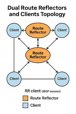
2. Dual Route Reflectors
Two RRs provide redundancy. Clients peer with both. This is more resilient, but comes with new challenges in route consistency. Clients may receive different best paths from each RR, depending on IGP metrics and RR state.
3. Hierarchical Route Reflectors
In very large-scale environments, RRs may be organized in tiers—core, aggregation, and access. Clients peer with local RRs, and RRs peer among themselves in a hierarchical fashion. This enables scalability while limiting the failure domain of any one RR.
4. Confederation + Route Reflectors
In very large ISPs or MPLS VPN deployments, Confederations are combined with RRs for even greater scalability. Each confederation sub-AS may have its own RRs, with inter-sub-AS peering maintained at the border.
iBGP Client Configuration: An Example
Let's take a simple topology with two route reflectors and three clients. Here's a configuration snippet from a Cisco device acting as a client:
router bgp 65000
 bgp log-neighbor-changes
 neighbor 10.0.0.1 remote-as 65000
 neighbor 10.0.0.1 route-reflector-client
 neighbor 10.0.0.2 remote-as 65000
 neighbor 10.0.0.2 route-reflector-client
The 'route-reflector-client' command tells the router that these neighbors can reflect routes to it. On the RR side, the same directive applies for each client peer.
Design Considerations
1. IGP Consistency
RRs select best paths based on BGP attributes and IGP metrics. If your IGP cost to clients varies significantly, your best path may be inconsistent across RRs. Keep the IGP stable and symmetric where possible.
2. BGP Attributes Preservation
By default, RRs do not modify most BGP attributes, but some attributes (like ORIGINATOR_ID and CLUSTER_LIST) are added to prevent loops. Be aware of how these attributes affect downstream policy and selection.
3. Convergence Tradeoffs
Reflectors reduce the number of iBGP sessions but may slow down convergence compared to full mesh. Route withdrawals may propagate more slowly. You may need to tune BGP timers or deploy BGP PIC (Prefix Independent Convergence) for improvement.
4. Cluster-ID Strategy
Each RR cluster must have a unique Cluster-ID to avoid loops. When multiple RRs are deployed in the same cluster, they must share the same Cluster-ID. Mismatches can cause routing blackholes or path inconsistencies.
Testing and Visibility
To validate your RR setup, use the following techniques:
- Check the BGP table for reflected prefixes using
show ip bgporshow bgp ipv4 unicast. - Inspect the CLUSTER_LIST and ORIGINATOR_ID fields for path loop prevention.
- Test route failover scenarios to ensure redundancy behaves as expected.
- Use
tracerouteorpingwith loose source routing to simulate asymmetric paths.
Operational Pitfalls
Some common issues when deploying RRs include:
- Clients accidentally configured as non-clients, leading to missing routes
- Route dampening policies incorrectly applied at the RR, causing route flaps
- Uneven path selection due to differing IGP metrics or missing MEDs
- Failure to reflect loopback reachability, breaking next-hop resolution
These can be addressed with a combination of peer-template configurations, strict prefix filtering, and route policies tailored for RR logic.
Visualization
Conclusion
Route Reflectors offer a scalable and efficient way to manage iBGP topologies, especially in networks that grow beyond a few dozen routers. However, they are not a silver bullet. Design decisions around redundancy, attribute propagation, and convergence must be deliberate. In Part 3, we’ll explore best practices and performance tuning techniques to optimize your BGP design further.